| Ch 5. Beam Deflections | Multimedia Engineering Mechanics | ||||||
|
Integration of Moment |
Integration of Load |
Method of Superposition |
Indeterminate Beams |
||||
| Method of Superposition | Case Intro | Theory | Case Solution | Example |
| Chapter |
| 1. Stress/Strain |
| 2. Torsion |
| 3. Beam Shr/Moment |
| 4. Beam Stresses |
| 5. Beam Deflections |
| 6. Beam-Advanced |
| 7. Stress Analysis |
| 8. Strain Analysis |
| 9. Columns |
| Appendix |
| Basic Math |
| Units |
| Basic Mechanics Eqs |
| Sections |
| Material Properties |
| Structural Shapes |
| Beam Equations |
| eBooks |
| Dynamics |
| Fluids |
| Math |
| Mechanics |
| Statics |
| Thermodynamics |
| ©Kurt Gramoll |
|
|
||
|
|
Previously, deflection at the tip of the equipment was determined by integrating both the moment equation and load-deflection equation. Both involved finding numerous integration constants. Using the method of superposition and basic beam deflection equations from the appendix, the tip deflection can be found without the integration. |
|
| Reducing Beam into Simpler Beams |
||
|
|
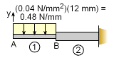
The main concept with superposition is to reduce a complex problem to simpler, smaller problems and then adding those solutions together. The current beam is a basic cantilever beam, but the changing beam cross section and loading makes it complex. First, checking with the appendix, it is noted that there is no solution for this type of beam. Thus it must be simplified. One possible method is to split the beam into two parts at point B, similar with the integration methods previously used. |
|
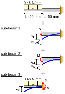 Equivalent Beam Deflections Using Superposition Principle |
It is important that each of the simplified beam sections (sub-beams) are in the appendix (or handbook). This beam has been split into three sub-beams: 1) cantilever with a point load, 2) cantilever with a moment load, and 3) cantilever with a distributed load. (The beam could be split into other sub-beam combinations.) Notice that the beam loading has also been distributed to the sub-beams. The equivalent loading for the uniform distributed load on the right sub-beam is P = [(0.04 N/mm2)(12 mm)] (50
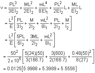
mm) M = F d These loads are also the internal shear and moment at the joint between the sub-beams. Sub-beam 3) is modeled as a cantilever beam since its deflection will be in additional to the deflection of the right beam section. The total deflection will be vtotal = vP + vM + vw + θP L + θM L The δ terms are straight forward and simply added together. The right beam also rotates (θP + θM) at its tip due to the point load,P, and moment load, M. These rotations will cause added deflection for the left sub-beam. |
|
| Properties |
||
|
|
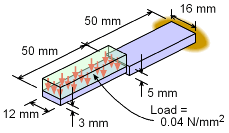
Before using the deflection equations from the appendix, the moment of inertia needs to be calculated. Using the equation for a rectangular cross section gives, I1 = 12(3)3/12 = 27.0 mm4 I2 = 16(5)3/12 = 166.7 mm4 The material stiffness, E, is given as E = 200 GPa = 200×109 N/m2 (1 m/1000 mm)2 = 200,000 N/mm2 |
|
| Deflection and Rotation Equations |
||
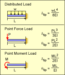 Basic Cantilever Beam Deflection and Rotation at Tip |
The deflection and rotation equations are listed in the Beam Equation appendix. They are summarized in the table at the left. Only the tip location is required, so the full deflection equation is not needed. Notice the cantilever beams shown at the left are reversed from the appendix listing, which is common. Substituting these relationships gives vtotal = vP + vM + vw + θP L + θM L As expected, this is the same deflection as previously calculated using the integration method. |
|
Practice Homework and Test problems now available in the 'Eng Mechanics' mobile app
Includes over 500 free problems with complete detailed solutions.
Available at the Google Play Store and Apple App Store.