| Ch 5. Beam Deflections | Multimedia Engineering Mechanics | ||||||
|
Integration of Moment |
Integration of Load |
Method of Superposition |
Indeterminate Beams |
||||
| Integration of Load Equation | Case Intro | Theory | Case Solution | Example |
| Chapter |
| 1. Stress/Strain |
| 2. Torsion |
| 3. Beam Shr/Moment |
| 4. Beam Stresses |
| 5. Beam Deflections |
| 6. Beam-Advanced |
| 7. Stress Analysis |
| 8. Strain Analysis |
| 9. Columns |
| Appendix |
| Basic Math |
| Units |
| Basic Mechanics Eqs |
| Sections |
| Material Properties |
| Structural Shapes |
| Beam Equations |
| eBooks |
| Dynamics |
| Fluids |
| Math |
| Mechanics |
| Statics |
| Thermodynamics |
| ©Kurt Gramoll |
|
|
||
|
|
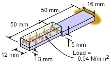
The deflection at the tip of the equipment can be determined by integrating the basic distributed load equation four times. There are actually four equations, one for each half since the load and beam structure differ in each section. A total of eight boundary conditions will be needed to solve the four integration constants for both equations. |
|
| Free-Body Diagram |
||
|
|
To help determine beam sections and boundary conditions, a free-body diagram should be constructed. Each change in beam geometry and load requires a new beam section and deflection equation. For this cantilever beam, there will be two sections, one from point A to B and a second section from point B to C. The uniform distributed load on the left part of the beam is w = (0.04 N/mm2)(12 mm) = 0.48 N/mm The actual values of the reactions do not need to be determined which is one of the advantages of this method. |
|
| Beam Properties |
||
|
|
The moment of inertia using the equation for a rectangular cross section gives, I1 = 12(3)3/12 = 27.0 mm4 I2 = 16(5)3/12 = 166.7 mm4 The material stiffness, E, is given as E = 200 GPa = 200×109 N/m2 (1 m/1000 mm)2 = 200,000 N/mm2 |
|
| Integrating the Load-Deflection Equations |
||
|
The deflection of any beam can be found by integrating the basic load-deflection differential equation, EIv´´´´ = -w(x) for each beam section. Section 1 (from point A to B) EIv1´´´´ = -0.48 N/mm Note that EIv´´´ is the shear and EIv´´ is the moment. This will be needed when applying the boundary conditions. Section 2 (from point B to C) EIv2´´´´ =
0 N/mm |
||
| Boundary Conditions |
||
 Eight Boundary Conditions |
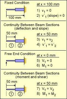
There are eight constants of integrating that need to be defined. This requires eight boundary conditions. The first two conditions are due to the fixed joint at the right end. This requires both the deflections, v, and the slope, v´, to be zero. These are listed in the table at the left as conditions 1) and 2). The next two conditions are due to continuity between beam sections 1 and 2. Since the beam is continuous, the beam deflection and slope on either side of the joint must be equal. Conditions 5 and 6 are from the free end which cannot have any shear or moment. And finally, similar to slope and deflection, the shear and moment need to be the same between beam sections 1 and 2. The shear is the the same since there is no point load at the joint. Likewise, the moment is the same since there is no applied point moment at the joint. |
|
| Determining Constants |
||
|
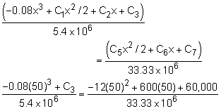
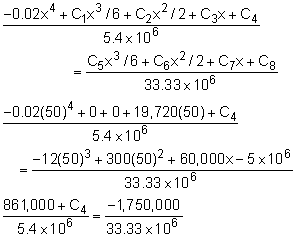
With the eight boundary conditions defined, eight equations can now be constructed. Generally, boundary conditions can be applied so that only one constant is present in a given equation. However, sometimes two or three equations will need to be solved simultaneously. Boundary Condition 5) V1 = 0 at x = 0 mm Boundary Condition 6) M1 = 0 at x = 0 mm Boundary Condition 7) V1 = V2 at x =
50 mm Boundary Condition 8) M1 = M2 at x =
50 mm Boundary Condition 2) v´2 = 0 at x = 100 mm
Boundary Condition 1) v2 = 0 at x = 100 mm |
||
|
Boundary Condition 4) v´1 = v´2 at x =
50 mm Boundary Condition 3) v1 = v2 at x = 50 mm |
||
| Final Deflection Equations |
||
 Final Deflection Curve |
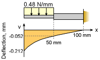
The final deflection equations for both beam sections are v1 = -3.704×10-9x4 + 0.003652x - 0.2119 mm v2 = -1.2×10-7x3 + 9.0×10-6x2 + 0.0018x - 0.15 mm The maximum deflection at the tip (x = 0) is vx=0 = -0.2119 mm This is the same (within rounding error) of the previous solution. |
|
Practice Homework and Test problems now available in the 'Eng Mechanics' mobile app
Includes over 500 free problems with complete detailed solutions.
Available at the Google Play Store and Apple App Store.
