| Ch 2. Torsion | Multimedia Engineering Mechanics | ||||||
|
Circular Bars |
Nonuniform & Indeterminate |
Thin-walled Tubes |
Non-Circular Bars | ||||
| Nonuniform & Indeterminate Torsion | Case Intro | Theory | Case Solution | Example |
| Chapter |
| 1. Stress/Strain |
| 2. Torsion |
| 3. Beam Shr/Moment |
| 4. Beam Stresses |
| 5. Beam Deflections |
| 6. Beam-Advanced |
| 7. Stress Analysis |
| 8. Strain Analysis |
| 9. Columns |
| Appendix |
| Basic Math |
| Units |
| Basic Mechanics Eqs |
| Sections |
| Material Properties |
| Structural Shapes |
| Beam Equations |
| eBooks |
| Dynamics |
| Fluids |
| Math |
| Mechanics |
| Statics |
| Thermodynamics |
| ©Kurt Gramoll |
|
|
||
|
|
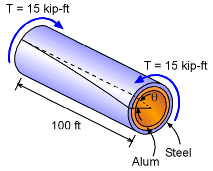
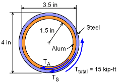
The drilling shaft is constructed from two different materials, steel and aluminum. Each material section is 0.25 inches thick with the steel on the outside. The applied torque is 15 kip-ft (equal to 15,000 lb-ft) and is constant along the 100 foot pipe length. As the diagram at the left shows, the angle of twist, θ, will be the same for both materials at any given location along the pipe. This condition is critical in solving for the stresses. |
|
| Shear Stiffness and Polar Moment of Inertia |
||
|
Before developing the basic equations, there are several constants that are needed. The first is the shear stiffness, G. Recall, G can be calculated from E and ν, giving The polar moment of inertia call also be calculated for each material section. |
||
| Torque Distribution in Each Section |
||
|
|
The drilling shaft maintains a torque or moment of 15 kip-ft but the amount of the torque in each of the two sections is not known. Summing the moments around the pipe axis gives TA + TS = Ttotal = 15 kip-ft Thus, there are two unknowns but only one equation from static equilibrium. A second equation can be developed from the angle of twist compatibility relationship. Each section must twist the same, or θsteel = θalum Recall, the angle of twist for any circular shaft is Using this in the compatibility equation gives Rearranging and substituting values gives TS = 4.586 TA This indicates the steel section takes almost 80% of the torque. Thus, the aluminum will not help much. This result can be substituted back into the moment equilibrium equation, giving TA + 4.586 TA = 15,000 lb-ft TA = 2,685 lb-ft TS = 12,310 lb-ft |
|
| Stresses |
||
|
The stresses in each of the two sections can now be determined using the torsion stress equation. The maximum stress occurs at the outer edge of each section |
||
 Shear Stress in Two-Part Drilling Pipe |
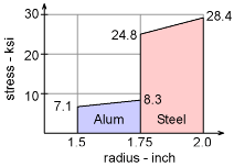
tS-max = 14.2 (2) = 28.40 ksi tA-max = 4.752 (1.75) = 8.316 ksi To better understand the stress distribution, the diagram at the left shows the shear stress as a function of the radius. Notice, there is a discontinuity at the interface between the material sections. The angle of twist and strain is equal at the interface, but the stresses are not. |
|
Practice Homework and Test problems now available in the 'Eng Mechanics' mobile app
Includes over 500 free problems with complete detailed solutions.
Available at the Google Play Store and Apple App Store.


