|
|
STATICS - THEORY
|
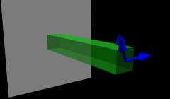
3D Internal Forces and Moments
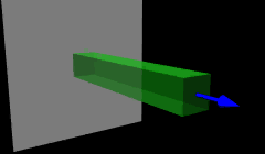
3D Force Components
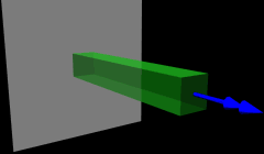
3D Moment Components
|
|
Internal loads in a structural member are the result of externally applied loads. The external loads are transmitted to different parts of the structure through these internal loads.
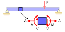
The internal loads can be determined by the method of sections. A member is cut at the point of interest, and the internal loads are revealed as equivalent external loads.
Since the member was in equilibrium before being cut, these equivalent external loads must keep the member in equilibrium.
In general 3D, internal loads have three force components (one normal and two shear) and three moment components (one twisting and two bending).
For the common 2D case, there are two forces, an axial force and a shear force, plus one moment. These forces and moments are shown in the diagram below.
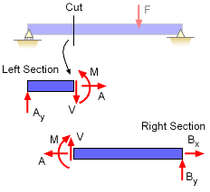
Unknown Internal Loads, V, A, and M Replace
Deleted 2D Structure Section to Maintain Equilibrium |
| |
|
|
| |
|
Sign Convention
|
Standard Positive Sign Convention for
Internal Shear, Moment and Axial Force |
|
After the member is cut, a free-body diagram can be drawn for either section, but unknown equivalent external loads must be included to maintain equilibrium. A correct and consistent sign convention for the internal loads must be used when we draw the free-body diagram. The sign convention shown at the left describes what is meant by a positive force or moment. This convention is the most common sign convention for forces and moments.
Forces and moments acting in the direction shown are considered to be positive. |
| |
|
|
| |
|
Solving for Internal Forces
|

Cut Location |
|
Before solving for internal loads, the external reaction generally need to be determined. This is done with the normal equilibrium equations applied to the completed structure.
The first step in determining internal loads, is to make a cut at the desired location. Each location can have different internal loads.
After the cut is done, a free-body diagram is drawn for one of the two sections (generally a right and left section. Remember to replace the removed section with unknown the internal loads. The internal loads can now be determined by letting the sum of forces and sum of moments equal zero. If there are axial loads, then also sum forces along the direction of the member.
Internal loads can be calculated on either face of a cut section. The values calculated for the two faces must be identical since they are actually the same location.
In the following example, the internal forces at the cut location are found by cutting the beam and solving for either the piece to the left of the cut or the piece to the right of the cut. |
| |
|
|
| |
|
Left Side of Cut
|

Left Section |
|
If the left section is used, then a free-body diagram should be drawn for just that section, as shown at the left. Notice that the internal forces are required to insure the left section stays in equilibrium without the right section. The direction of the moment and shear are according to the proper sign convention.
The axial internal force is not drawn since there are no axial external loads. The axial internal load is zero for all location in this example.
If the the forces in the vertical direction are summed, then the shear force V1 is
ΣFy
= 0
Ay - V1 = 0 ==>
V1 = Ay
Next, summing the moments about the cut, the bending moment,
M1, can be determined,
ΣMcut = 0
M1 - a Ay = 0 ==> M1 = a Ay
Recall, the reaction force Ay is determined before the cut is made and is considered a known quantity. |
| |
|
|
| |
|
Right Side of Cut
|
|

Right Section
|
|
If the section to the right side of the cut is used, the free-body diagram will be of only the right section of the beam as shown at the left. Again notice that the internal forces are drawn according to the sign convention.
Summing the forces in the vertical direction, gives
ΣFy = 0
By - F + V2 = 0 ==> V2 = F - By
Summing the moments about the cut gives
ΣMcut = 0
c By - b F - M2 = 0
M2 = c By - b F
Since both methods calculate the shear and moment at cut, the results must be the same. |
| |
|
|
|


