| Ch 8. Strain Analysis | Multimedia Engineering Mechanics | ||||||
|
Plane Strain |
Mohr's Circle for Strain |
Strain Gages |
|||||
| Plane Strain and Principal Strains | Case Intro | Theory | Case Solution | Example |
| Chapter |
| 1. Stress/Strain |
| 2. Torsion |
| 3. Beam Shr/Moment |
| 4. Beam Stresses |
| 5. Beam Deflections |
| 6. Beam-Advanced |
| 7. Stress Analysis |
| 8. Strain Analysis |
| 9. Columns |
| Appendix |
| Basic Math |
| Units |
| Basic Mechanics Eqs |
| Sections |
| Material Properties |
| Structural Shapes |
| Beam Equations |
| eBooks |
| Dynamics |
| Fluids |
| Math |
| Mechanics |
| Statics |
| Thermodynamics |
| ©Kurt Gramoll |
|
|
||||||||||||||||||||||
|
|
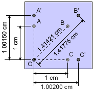
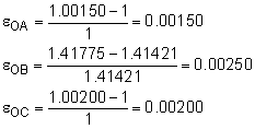
The distance between points A, B, C and O are measured using a laser device before and after the bracket is loaded. The results are listed in the table below.
These displacements can be used to find the normal strain in the direction of OA, OB, and OC. Then, the strains can be analyzed using the strain transformation equations. Finally, the maximum shear strain can be determined. |
|||||||||||||||||||||
| Normal Strains |
||||||||||||||||||||||
 Normal Strain Between Points |
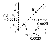
Since the distance before and after loading are known, the normal strains can be determined as The εOA and εOC are in the direction of the y-axis and x-axis, respectively. Also, the strain εOB is in the direction of the new rotated coordinate x´. This gives εOA = εy = 0.00150 = 1,500 μ εOB = εx´ = 0.00250 = 2,500 μ εOC = εx = 0.00200 = 2,000 μ Since strain is generally a very small number, the symbol μ "micro-strain" is commonly used to represent 10-6. This symbol does not represent units, and strain is still unit-less. |
|||||||||||||||||||||
| Rotating Strains |
||||||||||||||||||||||
|
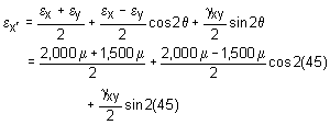
The stress element needs to be rotated 45o in the positive direction. Using the stress transformation equations, the stresses in the new x'-y' coordinate system will be, 2,500 μ = 1,750 μ + 0 + γxy/2 γxy = 750 μ = 0.000750 |
||||||||||||||||||||||
| Maximum Shear Strain |
||||||||||||||||||||||
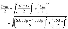
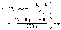
|
The maximum shear strain can be found by γmax = 450.7μ = 0.0004507 The maximum shear strain will on a plane that is rotated θγ-max. That angle is, θγ-max = -16.85o |
||||||||||||||||||||||
Practice Homework and Test problems now available in the 'Eng Mechanics' mobile app
Includes over 500 free problems with complete detailed solutions.
Available at the Google Play Store and Apple App Store.