| Ch 2. Torsion | Multimedia Engineering Mechanics | ||||||
|
Circular Bars |
Nonuniform & Indeterminate |
Thin-walled Tubes |
Non-Circular Bars | ||||
| Thin-walled Tubes | Case Intro | Theory | Case Solution | Example |
| Chapter |
| 1. Stress/Strain |
| 2. Torsion |
| 3. Beam Shr/Moment |
| 4. Beam Stresses |
| 5. Beam Deflections |
| 6. Beam-Advanced |
| 7. Stress Analysis |
| 8. Strain Analysis |
| 9. Columns |
| Appendix |
| Basic Math |
| Units |
| Basic Mechanics Eqs |
| Sections |
| Material Properties |
| Structural Shapes |
| Beam Equations |
| eBooks |
| Dynamics |
| Fluids |
| Math |
| Mechanics |
| Statics |
| Thermodynamics |
| ©Kurt Gramoll |
|
|
|||||
| Torsion of Thin-Walled Tubes |
|||||
|
|
Even though exact solution for the shear stress and angle of twist for noncircular tubes requires complex analysis (beyond this section), approximate solutions can be developed for thin-walled tubes. The first assumption is that the wall tube is thin when compared to the tube radius. One rule of thumb is the thickness should be less than 10% of the smallest overall external dimension. Second, tube does not have any cut or slice. In other words, it is continuous around the radius. The tube does not need to be circular but it should not have severe reverse curvature. Some acceptable cross sections are shown in the diagram at the left. Also, the thickness does not need to be constant. |
||||
| Shear Flow in Thin-Walled Tubes |
|||||
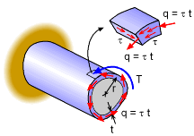 Shear Flow, q, around a closed tube due to an applied Moment, T |
To analyze thin-walled tubes, the concept of shear flow, q, needs to be understood. When a moment (or torque) load, T, is applied to a thin-walled tube, the load is distributed around the tube as a shear stress, τ. But this is a difficult value to deal with since it is not constant. A better value is the shear flow, which is simply the stress multiplied by the changing thickness, t.
The units of shear flow are force per unit length. This represents the force per length acting around the tube caused by the moment as shown in the diagram at the left. Even though both the thickness, t, and the shear stress, τ, vary around the tube, the shear flow will be constant. This can be proven by applying static equilibrium equations acting on a small infinitesimal element, which is not included here. However, if one just notices that shear flow must "flow" around the tube, then for any tube section length, the flow shear "in" must equal the shear flow "out". This is a simplification of the shear flow, but shows that shear flow must be constant around the tube. |
||||
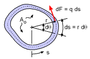 Force element, dF, acting along tube edge due to applied Moment |
The shear flow multiplied by an arc length of the tube, ds, will give a force. This force, dF, causes a moment, dT, about the tube center. Summing all the moments caused by all the differential lengths, ds, will give the total applied moment, T. The integral symbol with the circle just means that the integration is around a closed path. Since the shear flow, q, is constant, it simplifies to |
||||
|
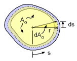
Even though the integral looks simply, it cannot be solved for most noncircular tubes. Thus, the integral needs to be related to something else so that it can be eliminated. One possibility is to use the total cross sectional area, Ao, of the tube. For a small element, the area of the triangular section, dAo, is approximately, dAo = 0.5 r ds The total area can be calculated by integration over the total tube cross section length, S, giving, Note that all calculations are done at the middle of the tube thickness for simplification. Again, it is assumed that the thickness is much smaller than the radius so using the inside, middle or outside surface to determine the total area is approximately the same. Now that the integral has been found to be equal to 2Ao, it can be substituted into the original integral equation to give, q (2Ao) = T Rearranging gives, |
||||
| Angle of Twist in Thin-Walled Tubes |
|||||
|
The angle of twist for a closed thin tube with a noncircular cross section can be developed using energy methods along with the previous derived equations. The basic idea is to determine the strain energy in an infinitesimal element, sum it over the whole tube and then equate it to the work energy needed to twist the tube. Sounds complex, but is not too bad. |
|||||
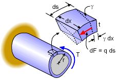 Tube element undergoing deformation |
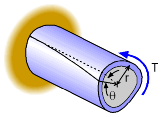
First, start with a small element from a typical tube that is undergoing deformation as shown in the diagram at the left. The stored strain energy for this can be found from using the basic concept that energy is equal to a force operating through a distance, or simply U = F • L. For the small infinitesimal element, ds by dx, the force causing the deformation is dP ( = q ds). At the base, the deformation is zero and at the free end is (γ ds). Thus the average deformation is simply (γ dx)/2. The total strain energy for the element is dU = [dP] [0.5 (γ ds)] = (q ds)(γ ds)/2 = q γ (ds)2/2 Recall from Hooke's law, γ = τ/G. Also, the shear stress, τ, is related to the shear flow, τ = q/t. Substituting these relationships into the energy equation gives, |
||||
 Tube element undergoing deformation |
This can now be integrated over the length of the tube, L, and around the circumference of the tube. This gives, The energy caused by the applied moment is simply U = Tθ/2 where θ is the angle of twist in radians. Using this condition and the shear flow relationship, q =T/(2Ao), gives, rearranging gives the final angle of twist equation as, |
||||
If the thickness t is constant, then the angle of twist becomes
where S is the total length of the median circumference of the tube. The angle is in radians. The angle of twist equation can also be used in parts if sections of the tube have constant thickness. In other words, each section length, Si, is used to determine θi, and then they are added together. It is important to note that large torsion loads on thin tubes will also cause buckling. Buckling of tube is a complex topic and not covered here. However, it needs to be checked if large torsion loads are expected on thin-walled tubes. |
|||||
Practice Homework and Test problems now available in the 'Eng Mechanics' mobile app
Includes over 500 free problems with complete detailed solutions.
Available at the Google Play Store and Apple App Store.

