| Ch 4. Beam Stresses | Multimedia Engineering Mechanics | ||||||
|
Bending Strain and Stress |
Beam Design |
Shear Stress |
Built-up Beams |
||||
| Built-up Beams | Case Intro | Theory | Case Solution | Example |
| Chapter |
| 1. Stress/Strain |
| 2. Torsion |
| 3. Beam Shr/Moment |
| 4. Beam Stresses |
| 5. Beam Deflections |
| 6. Beam-Advanced |
| 7. Stress Analysis |
| 8. Strain Analysis |
| 9. Columns |
| Appendix |
| Basic Math |
| Units |
| Basic Mechanics Eqs |
| Sections |
| Material Properties |
| Structural Shapes |
| Beam Equations |
| eBooks |
| Dynamics |
| Fluids |
| Math |
| Mechanics |
| Statics |
| Thermodynamics |
| ©Kurt Gramoll |
|
|
||
|
|
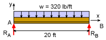
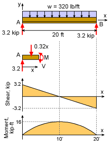
The roof of a new room addition supports 80 lb/ft2 roof load. The 20 ft long box beams are evenly spaced every 4 ft. Thus the total load on a single beam (not end beams) is w = (80 lb/ft2) (4 ft) = 320 lb/ft The wall reaction forces are equal due to symmetry. RA = RB = (320 lb/ft)(20 ft)/2 = 3,200 lb = 3.2 kip |
|
| Shear and Moment Diagrams |
||
|
|
A shear and moment diagram of the channel will help identify the maximum shear and moment. Both of these values are needed to determine the maximum shear and bending stress. Only one cut is needed due to the continuous loading. ΣF = 0 ΣM = 0 The shear load is maximum at each end of the beam (this is one reason old wood beams crack near the center at each end). To design the screw spacing, it is best to take the worst load, 3,200 lb, even though it changes along the beam. The maximum moment, 16.0 kip-ft, occurs at the beam mid-point. |
|
| Shear Stress |
||
|
|
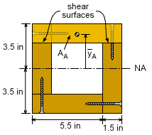
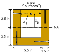
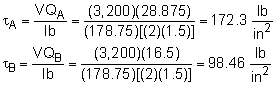
There are two possible location to shear the screws. The first location is the horizontal joints and involves the full top section (label Area A in first diagram). The left side is part of the left 2x6 and it is assumed the wood will not shear. The second location is the vertical joints and involves only part of the top section (label Area B in the second diagram). In both cases, there are two surfaces that will carry the shear load. First determine Q for both cases. QA = AAyA = (7.0)(1.5)(3.5 - 0.75) = 28.875 in3 QB = AByB = (4.0)(1.5)(3.5 - 0.75) = 16.5 in3 Next, the moment of inertia for the full cross sections needs to be known. I = 7(7)3/12 - 4(4)3/12 = 178.75 in4 Using the shear stress equation gives, This shear stress needs to be carried by the screws. Each screw can carry 800 lb. The minimum spacing (sA and sB) of the screws can be found using FScrew = τ A For each surface, this gives the spacing as 800 lb = (172.3 lb/in2) [(1.5 in)
sA] 800 lb = (98.46 lb/in2) [(1.5 in) sB] Thus, the screws should be every 3 inches on the horizontal joints and every
5 inches on the vertical surfaces. |
|
| Bending Stress |
||
|
The bending stress should also be checked. Unlike shear stress, the maximum bending stress occurs at the point furthest from the neutral axis. This is at the top or bottom surface. Using the bending stress equation gives, σ = -My/I This is lower than the allowable bending stress for wood so it should be safe. |
||
Practice Homework and Test problems now available in the 'Eng Mechanics' mobile app
Includes over 500 free problems with complete detailed solutions.
Available at the Google Play Store and Apple App Store.