| Ch 3. Beam Shear/Moment Diagrams | Multimedia Engineering Mechanics | ||||||
|
Shear and Moment |
Shear/Moment Diagrams |
Moving Loads |
|||||
| Moving Loads | Case Intro | Theory | Case Solution |
| Chapter |
| 1. Stress/Strain |
| 2. Torsion |
| 3. Beam Shr/Moment |
| 4. Beam Stresses |
| 5. Beam Deflections |
| 6. Beam-Advanced |
| 7. Stress Analysis |
| 8. Strain Analysis |
| 9. Columns |
| Appendix |
| Basic Math |
| Units |
| Basic Equations |
| Sections |
| Material Properties |
| Structural Shapes |
| Beam Equations |
| Search |
| eBooks |
| Dynamics |
| Fluids |
| Math |
| Mechanics |
| Statics |
| Thermodynamics |
| Author(s): |
| Kurt Gramoll |
| ©Kurt Gramoll |
|
|
|||||
| Introduction |
|||||
 Variable Location for Multiple Point Loads |
A common beam loading is a truck moving across a simply support bridge structure. The difficulty is the truck, or other vehicle loading, can be at any location on the beam. Thus, a method needs to be developed to determine the largest shear and moment for any location of the truck. |
||||
| Maximum Shear Force |
|||||
|
|
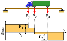
The shear diagram is fairly simple for point loads on a simply supported beam. The shear diagram equals the reaction at the two ends, and then the shear reduces in steps at each of the point loads as shown in the diagram on the left. The diagram shows three point loads, but the same general form of the shear diagram will hold true for more or less point loads. The general shear diagram indicates that the maximum shear force will occur at one of the two supports. The worse reaction force at either end of a simply support beam will occur when the loads are closest to that support. Thus, the maximum shear force will happen when the truck is at one end of the beam or the other as shown in the diagram. Both cases need to be checked to find the absolute maximum shear load. |
||||
| Maximum Bending Moment |
|||||
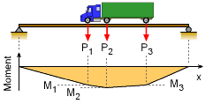
 Typical Moment Diagram for a Series of Point Loads |
Finding the maximum bending moment for a series of point loads on a simply support beam is not an easy process, especially since the loads can be located anywhere along the beam. To help with the analysis, it is assumed that distance between the point loads do not vary, which is the case for truck loading on a beam. Also, it helps with the analysis to note that the largest moments will occur directly under one of the point loads as can be seen in the diagram on the left. As would be expected, the largest point load will generally cause the largest moment under its location. This would be easy to determine if the truck (or point loads) location was fixed, but it is moving. |
||||
The first step is to determine the location of the truck that will give the largest moment for a given load. There is no single truck location that will maximize the moment for all loads at the same time. This means each load will have its own truck location that will maximize the moment under its position. |
|||||
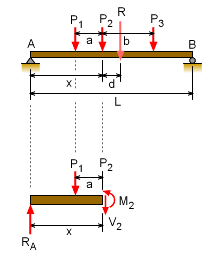
 Finding the Location of the Point Loads and the Maximum Moment under Load P2 |
The location of the truck (or point loads) that will maximize the moment for a particular load are found first finding the resultant force and its location with respect to that load. In the diagram on the left, load P2 is used to illustrate the calculation process. Assuming R and d are known, the reaction at the left end is ΣMB = 0 = -LRA + R(L - d - x) Next, summing moment at the cut at P2 (remember, the maximum is under the load), gives M2 = x RA - a P1 The maximum location will occur when dM2/dx = 0 = R (L - d - 2x)/L Therefore, the maximum is when This is true for any particular load and for any number of loads. Even though three loads were used in this example, the number of loads does not effect the maximum location. |
||||
In summary, the maximum bending moment under a particular load will occur when the center of the beam is midway between that load and the resultant of all loads acting on the span. It is important to remember, each load will have a different x. Each load must be analyzed by finding its x location and its maximum. Then the largest moment from each load can be used to design the beam. |
|||||
Practice Homework and Test problems now available in the 'Eng Mechanics' mobile app
Includes over 500 free problems with complete detailed solutions.
Available at the Google Play Store and Apple App Store.

