| Ch 1. Stress and Strain | Multimedia Engineering Mechanics | ||||||
|
Normal Stress |
Shear and Bearing Stress |
Normal Strain |
Hooke's Law |
Thermal Effects |
Indeterminate Structures |
||
| Shear and Bearing Stress | Case Intro | Theory | Case Solution | Example |
| Chapter |
| 1. Stress/Strain |
| 2. Torsion |
| 3. Beam Shr/Moment |
| 4. Beam Stresses |
| 5. Beam Deflections |
| 6. Beam-Advanced |
| 7. Stress Analysis |
| 8. Strain Analysis |
| 9. Columns |
| Appendix |
| Basic Math |
| Units |
| Basic Mechanics Eqs |
| Sections |
| Material Properties |
| Structural Shapes |
| Beam Equations |
| eBooks |
| Dynamics |
| Fluids |
| Math |
| Mechanics |
| Statics |
| Thermodynamics |
| ©Kurt Gramoll |
|
|
||
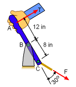
Handbrake Mechanism |
Example |
|
|
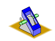
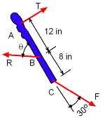
A handbrake is designed to pivot about point B while connected to control rod at C as shown in the diagram on the left. What is the maximum force, T, that can be applied at A if the shear stress in the pin at B and axial stress in the control rod at C is limited to 12.5 ksi and 5 ksi, respectively? Assume the diameter of the circular rod and the pin is 1 in and 0.5 in, respectively. |
||
| Solution |
||
|
|
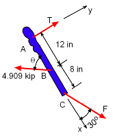
The applied force T may cause either shear failure in the pin at B or axial failure in the control rod at C. Shear failure will occur when shear stress in the pin at B exceeds 12.5 ksi. Since this stress is applied on two sides of same cross-section of the pin, the maximum allowable shear force is Axial failure will occur when axial stress in the control rod at C exceeds 5 ksi. The maximum allowable axial force in the control rod is For convenience, it is assumed that the pin at B will fail in shear stress before the rod at C will fail in axial stress. The axial force, F, at this stress state will be determined and compared with Fmax . If F is less than or equal to Fmax, the assumption is correct. Otherwise the failure will occur due to axial stress and the value of T will have to be recalculated. Since it is assumed the pin at B will fail first, the force at B is set at 4.909 kip at an angle of θ, as shown at the left. Notice the x-y coordinates are orientated in the handbrake direction. There are three unknowns, F, T and θ. |
|
|
Since it is assumed the pin at B will fail first, the force at B is set at 4.909 kip with an unknown angle of θ, as shown at the left. Notice the x-y coordinates are orientated in the handbrake direction. There are three unknowns, F, T and θ. Summing all forces in x direction, ΣFx = 0, gives F cos30 = 4.909 cosθ Summing all forces in y direction, ΣFy = 0, gives T = 4.909 sinθ - F sin30 Summing all moments about B, ΣMB = 0, gives (T)(12) = (Fsin30)(8) Combining last two equations, 0.3333 F = 4,909 sinθ - 0.5 F Replacing F in the first equation, 5.669 cosθ = 5.891 sinθ Calculating for axial force, F = 5,891 sin43.90 Hence, the assumption for failure is not correct and it is obvious that the failure will occur due to axial stress. |
|
|
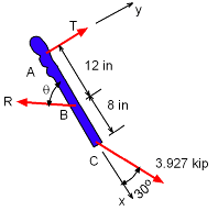
Since the control rod at C will fail first, the force at C is now set at 3.927 kip. There are three unknowns, R, T and θ. To determine the value of T, calculations with other two unknowns can be easily avoided by taking summation of all moments about B. ΣMB = 0, gives, (T)(12) = (Fsin30)(8) T = 1,309 lb |
|
Practice Homework and Test problems now available in the 'Eng Mechanics' mobile app
Includes over 500 free problems with complete detailed solutions.
Available at the Google Play Store and Apple App Store.
