| Ch 1. Stress and Strain | Multimedia Engineering Mechanics | ||||||
|
Normal Stress |
Shear and Bearing Stress |
Normal Strain |
Hooke's Law |
Thermal Effects |
Indeterminate Structures |
||
| Normal Stress | Case Intro | Theory | Case Solution | Example |
| Chapter |
| 1. Stress/Strain |
| 2. Torsion |
| 3. Beam Shr/Moment |
| 4. Beam Stresses |
| 5. Beam Deflections |
| 6. Beam-Advanced |
| 7. Stress Analysis |
| 8. Strain Analysis |
| 9. Columns |
| Appendix |
| Basic Math |
| Units |
| Basic Mechanics Eqs |
| Sections |
| Material Properties |
| Structural Shapes |
| Beam Equations |
| eBooks |
| Dynamics |
| Fluids |
| Math |
| Mechanics |
| Statics |
| Thermodynamics |
| ©Kurt Gramoll |
|
|
|||||||||||||||||||||||||||
| Introduction |
|||||||||||||||||||||||||||
|
| Mechanics of Materials presents topics that build on the concepts learned in your Statics course. In general, this course introduces stress and strain (both normal and shear) for basic structural members (beams, shafts, columns and axial rods), deflection of beams, column buckling and material failure. Similar to all engineering courses, there are also many sub-topics. This course is critical to structural engineers, product reliability engineers, and equipment design engineers. Without a good knowledge of stress and strain, and how they can be calculated, no structure can be well designed and premature failures can and probably will occur. |
||||||||||||||||||||||||||
| Static Equilibrium |
|||||||||||||||||||||||||||
 |
Mechanics of Materials starts with the basic static equilibrium equations,
Each object in any static structure must be in both force and moment equilibrium. These equations are used in almost every problem in mechanics to calculate needed information, such as support reactions, internal forces, equivalent loads and shear. Another tool used extensively in mechanics is the Free Body Diagram (FBD). These diagrams isolate a single member or structure with all boundary conditions converted to forces and moments. A FBD helps to identify all loads, forces and moments (both known and unknown) on a object which can then be used to solve for unknowns. |
||||||||||||||||||||||||||
| Problem Solving |
|||||||||||||||||||||||||||
 Steps in Solving Problems |
In engineering, following a set procedure in solving problems saves time and decreases the number of errors. Generally, the following five steps will help solve problems in mechanics.
| ||||||||||||||||||||||||||
| Units |
|||||||||||||||||||||||||||
|
Whether we like it or not, engineers must be able to work in both US and SI (metric) units. Conversion ratios relate one set of units to another set and are commonly used to quickly convert between units. Some basic ratios are shown at the left. The Units Appendix has a large selection of conversion ratios for both SI and US units. | ||||||||||||||||||||||||||
| Normal Stress |
|||||||||||||||||||||||||||
 Normal Stress |
The most common type of stress in mechanics is a normal stress. A stress is defined as the load divided by the area. For a normal stress, it is all loads perpendicular to the surface. (non-perpendicular loads are addressed in later sections). This relationship can be summarized as
Another way to express the same concept is to define the total perpendicular load P as where A is the area of the surface. The symbol σ is used for normal stress. Later, other symbol, such as τ, are used for other types of stress |
||||||||||||||||||||||||||
| Stress on an Inclined Plane |
|||||||||||||||||||||||||||
 Stress on an Inclined Plane |
In many cases, the stress needs to be determined on a plane that is not perpendicular to the load direction. This can obtained by using trigonometry relations, but remember, both the area and load needs to be rotated to the inclined plane. N = P cosθ Using the definition of normal stress, the stress perpendicular to the inclined plane is
The stress parallel to the plane (referred to as shear stress) is
|
||||||||||||||||||||||||||
| Saint-Venant Principle |
|||||||||||||||||||||||||||
 Stress Distribution in a Tensile Test |
The Saint-Venant Principle simply states that localized stress concentrations disappear a short distance from the concentration (after Barre de Saint-Venant, 1864). This means that the stress is uniform in a uniaxial loaded bar away from the ends. Generally, stress concentrations dissipate quickly. This is illustrated at the left for a square bar that is pulled using friction grips at both ends. The grips introduce the tensile load on the surface of the bar, but quickly, the stress is evenly distributed over the bar. The relationship, σ = P/A, is only valid away from boundary conditions that introduce stress concentrations. |
||||||||||||||||||||||||||
| Factor of Safety |
|||||||||||||||||||||||||||
In all design situations, a factor of safety needs to be considered to help insure the structure does not fail due to unforeseen conditions such as excessive loading, errors, and poor craftsmanship. Of course, including a factor of safety does not guarantee that the structure will not fail, but it does decrease the possibility of failure. Basically, a "factor of safety" (FS) is a multiplication constant that is applied to the calculated load to give a higher load.
In all cases, the FS is greater than 1. In most cases, the factor of safety will be 2 or 3. While a high factor of safety sounds good, the penalty will be an increase in weight. Another way to consider the FS of a structure is
where the failure stress is the stress level when the material will fail. Failure or ultimate stress levels for various materials can be found in handbooks (see Materials Properties appendix). The allowable stress is the stress found in the design calculations for the actual applied load. In addition to FS, some design codes talk about a "margin of safety" (MS). This is simply a FS less 1, or MS = FS - 1.0 |
|||||||||||||||||||||||||||
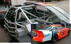 The internal structure of racing cars
 Practice Homework and Test problems now available in the 'Eng Mechanics' mobile app
Includes over 500 free problems with complete detailed solutions.
Available at the Google Play Store and Apple App Store.