| Ch 7. Incompressible and Inviscid Flow | Multimedia Engineering Fluids | ||||||
|
Bernoulli's Equation |
Flow Measurements |
Superposition of Flows |
Flow around Cylinder |
||||
| Bernoulli's Equation | Case Intro | Theory | Case Solution | Example |
| Chapter |
| 1. Basics |
| 2. Fluid Statics |
| 3. Kinematics |
| 4. Laws (Integral) |
| 5. Laws (Diff.) |
| 6. Modeling/Similitude |
| 7. Inviscid |
| 8. Viscous |
| 9. External Flow |
| 10. Open-Channel |
| Appendix |
| Basic Math |
| Units |
| Basic Fluid Eqs |
| Water/Air Tables |
| Sections |
| eBooks |
| Dynamics |
| Fluids |
| Math |
| Mechanics |
| Statics |
| Thermodynamics |
| ©Kurt Gramoll |
| |
|||||
In this section, Bernoulli's equation will be introduced. The details of the derivation are simplified, with attention focused on proper use of the equation. Restrictions on the application of Bernoulli's equation are also clearly stated to avoid misuse of the equation. A velocity measurement device called a Pitot tube will also be presented. In addition, the concept of energy and hydraulic grade lines will be introduced. |
|||||
| Bernoulli's Equation |
|||||
|
|
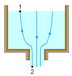
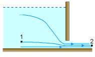
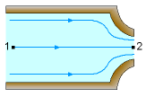
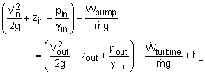
In the Conservation of Energy section, it was shown that for a control volume, the energy equation can be simplified to In many cases, the head loss (mainly due to viscous effects) can be ignored. If there is no pump or turbine in the system, then the equation becomes This relationship is a form of the Bernoulli's equation. The same relationship, but in a slightly different form, can be derived by applying conservation of momentum to a fluid element along any streamline in the flow, giving p + ρV2/2 + ρgz = constant along streamline where p is the static pressure, ρV2/2 is the dynamic pressure, and ρgz is
the
hydrostatic pressure. However, one should realize that Bernoulli's equation is subject
to some restrictions, and can only be applied to certain flow situations.
The assumptions made in deriving Bernoulli's equation are: |
||||
| Velocity at a Point using a Pitot Tube |
|||||
|
|
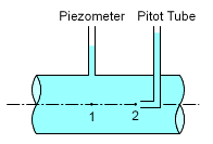
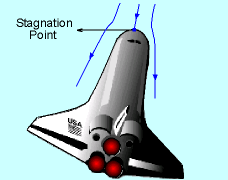
A combination of piezometer and pitot tube can be used to obtain the velocity at a specific point. Static pressure can be measured using a piezometer. The Pitot tube, as shown in the figure, can be used to measure the stagnation pressure. Stagnation pressure is the pressure when the flow has a stagnation velocity (i.e., V = 0). By perfectly aligning the Pitot tube with the flow, the flow will come to a stop at the tip of the Pitot tube, hence providing the stagnation pressure measurement. Applying Bernoulli's equation between points 1 and 2 as shown in the figure, and canceling the elevations (equal values) gives, |
||||
|
Since V2 = 0, the velocity at point 1 is where p1 and p2 are known from the height of the fluid column in the piezometer and Pitot tube, respectively. |
||||
| Energy and Hydraulic Grade Lines |
|||||
|
|
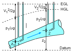
The energy grade line (EGL) and the hydraulic grade line (HGL) provide a graphical interpretation of Bernoulli's equation. The EGL represents the total head available with respect to a chosen datum (i.e., a reference line, as shown in the figure). Sometimes, this is also referred as the piezometric head and is the height a fluid column would rise in a piezometer. For example, the EGL and HGL for frictionless flow in a duct are shown in the figure. |
||||
