| Ch 10. Rankine Cycle | Multimedia Engineering Thermodynamics | ||||||
|
Rankine Cycle |
Reheat | Regeneration | Cogeneration | ||||
| Ideal Regenerative Rankine Cycle | Case Intro | Theory | Case Solution |
| Chapter |
| 1. Basics |
| 2. Pure Substances |
| 3. First Law |
| 4. Energy Analysis |
| 5. Second Law |
| 6. Entropy |
| 7. Exergy Analysis |
| 8. Gas Power Cyc |
| 9. Brayton Cycle |
| 10. Rankine Cycle |
| Appendix |
| Basic Math |
| Units |
| Thermo Tables |
| Search |
| eBooks |
| Dynamics |
| Fluids |
| Math |
| Mechanics |
| Statics |
| Thermodynamics |
| Author(s): |
| Meirong Huang |
| Kurt Gramoll |
| ©Kurt Gramoll |
| |
||
Steam power plants generate most of the electric power
in the world. To save fuel, efforts are constantly made to
improve the efficiency of the cycle on which steam power plants operate.
The general idea is to increase the fluid average temperature during
heat addition and decrease the fluid temperature during heat rejection.
This section will introduce one such cycle - the ideal regenerative
Rankine cycle, which increases the fluid average temperature during
the heat addition process. |
||
| Regeneration
|
||
|
|
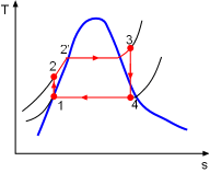
In a simple Rankine cycle, heat is added to the cycle during process
2-2'-3 (see the T-s diagram on the left). During this first stage (process
2-2'), the temperature of the water is low.
That reduces the average temperature during heat addition (process
2-2'-3). To remedy this shortcoming, increasing the temperature
of the feedwater (water leaving the pump and entering the boiler) can
be considered. This is accomplished by extracting stream from the turbine
to heat the feedwater. This process is called regeneration and the heat exchanger
where heat is transferred from steam to feedwater is called a
regenerator, or a feedwater heater. There are actually two main types of
feedwater heaters. If the steam mixes with the compressed water from
the pump, it is an open feedwater heater. If the
steam does not mix with the compressed water from the pump, it is a
closed feedwater heater. |
|
| Open Feedwater Heaters
|
||
|
Schematic of a Power Plant Running
|
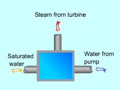
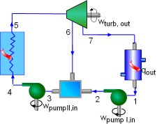
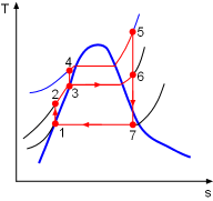
An open feedwater heater is basically a mixing chamber, where the steam extracted from the turbine mixes with the water exiting the pump. In an ideal condition, the water leaves the heater as a saturated liquid at the heater pressure. The schematic of a steam power plant with one open feedwater heater is shown on the left. In an ideal regenerative Rankine cycle with an open feedwater heater, steam from the boiler (state 5) expands in the turbine to an intermediate pressure (state 6). At this state, some of the steam is extracted and sent to the feedwater heater, while the remaining steam in the turbine continues to expand to the condenser pressure (state 7). Saturated water from the condenser (state 1) is pumped to the feedwater pressure and send to the feedwater heater (state 2). At the feedwater heater, the compressed water is mixed with the steam extracted from the turbine (state 6) and exits the feedwater heater as saturated water at the heater pressure (state 3). Then the saturated water is pumped to the boiler pressure by a second pump (state 4). The water is heated to a higher temperature in the boiler (state 5) and the cycle repeats again. The T-s diagram of this cycle is shown on the left. Note that the mass flow rate at each component is different.
If
1
kg steam
enters
the
turbine,
y kg
is extracted
to the
feedwater heater and (1-y) kg continues to expand to the condenser pressure.
So if the mass flow rate at the boiler is Condenser: For convenience, heat and work interactions for regenerative Rankine cycle is expressed per unit mass of steam flowing through the boiler. They are: Heat Input: qin = h5 - h4
Open feedwater heaters are simple and inexpensive, and can also
bring the feedwater to saturated state. However, each feedwater needs
a separate pump which adds to the cost. |
|
| Closed Feedwater Heaters
|
||
 A Closed Feedwater Click to View Movie (49 kB) 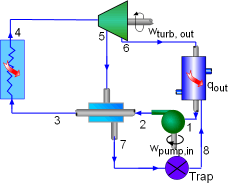 Schematic of a Power Plant Running an Ideal Regenerative Rankine Cycle with One Closed Feedwater Heater 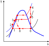 T-S Diagram of an Ideal Regenerative Rankine Cycle with One Closed Feedwater Heater |
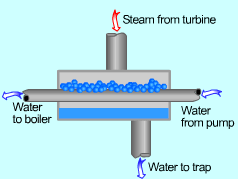
Closed feedwater heaters are shell-and-tube type recuperators in which feedwater temperature increases as the extracted steam condenses on the outside of the tubes carrying the feedwater. The two streams can be at different pressures since the two streams do not mix. The schematic of a steam power plant with one closed feedwater heater is shown on the left. In an ideal regenerative Rankine cycle with a closed feedwater, steam from the boiler (state 4) expands in the turbine to an intermediate pressure (state 5). Then some of the steam is extracted at this state and sent to the feedwater heater, while the remaining steam in the turbine continues to expand to the condenser pressure (state 6). The extracted stream (state 5) condenses in the closed feedwater while heating the feedwater from the pump. The heated feedwater (state 3) is send to the boiler and the condensate from the feedwater heater (state 7) is allowed to pass through a trap into a lower pressure heater or condenser (state 8). Another way of removing the condensate from the closed feedwater heater is pump the condensate forward to a higher-pressure point in the cycle.The T-s diagram of this cycle is shown on the left. Heat and work interactions for regenerative Rankine cycle with one closed feedwater heater is expressed per unit mass of water flowing through the boiler. They are: Heat Input: qin = h4 - h3 Compared with open feedwater heaters, closed feedwater heaters are more complex, and thus more expensive. Since the two streams do not mix in the heater, closed feedwater heaters do not require a separate pump for each heater. Most power plants use a combination of open and closed feedwater heaters. |
|
