| Ch 7. Exergy Analysis | Multimedia Engineering Thermodynamics | ||||||
| Exergy |
Exergy Change |
Exergy Balance(1) |
Exergy Balance(2) |
||||
| Exergy Balance (2) | Case Intro | Theory | Case Solution |
| Chapter |
| 1. Basics |
| 2. Pure Substances |
| 3. First Law |
| 4. Energy Analysis |
| 5. Second Law |
| 6. Entropy |
| 7. Exergy Analysis |
| 8. Gas Power Cyc |
| 9. Brayton Cycle |
| 10. Rankine Cycle |
| Appendix |
| Basic Math |
| Units |
| Thermo Tables |
| eBooks |
| Dynamics |
| Fluids |
| Math |
| Mechanics |
| Statics |
| Thermodynamics |
| ©Kurt Gramoll |
| |
||||||||||||||
| Exergy Balance for Control Volume
|
||||||||||||||
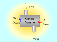 Exergy Balance for Control Volume |
The exergy balance for control volumes differ from those for closed systems in that they involve one more mechanism of exergy transfer: exergy transfer by mass transfer. Hence, the exergy balance for control volume can be developed by adding the net exergy transfer by mass on the right side of the relation of exergy balance for closed system. Recall, the exergy balance for closed system is:
Net exergy transfer by mass is: Therefore, the exergy balance for a control volume is:
where In rate form, the exergy balance for control volume is:
|
|||||||||||||
| Exergy Balance for Steady-Flow Systems
|
||||||||||||||
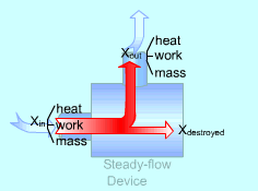 Exergy Balance for Steady-flow Device |
Most devices encountered in practice are steady-flow devices, such as turbines and nozzles. Their mass, energy, entropy and volume remain constants during a steady-flow process. Thus, its exergy does not change with time. dXCV/dt = 0 Then the rate form of exergy balance for a control volume undergoing a steady-flow process becomes
If it is an one-inlet-one-exit steady-flow device, the relation above further reduces to where the change in flow exergy is given by |
|||||||||||||
| Second-law Efficiency
|
||||||||||||||
Thermal efficiency and coefficient of performance for devices defined in previous sections are a measure of their performance. They are based on the first law of thermodynamics and referred to as the first-law efficiencies. The following gives the definition of the second-law efficiency. The second-law efficiency is defined as the ratio of the actual thermal
efficiency to the maximum possible (reversible) thermal efficiency under
the same condition (for
heat engine). It can be expressed as the ratio
of the useful work output and the maximum possible work output (for work-producing
device, such as turbine), or the ratio of the minimum work input to the
actual useful work input (for work-consuming device, such as compressor).
For refrigerators or heat Pumps,
it is defined in terms of the coefficient of performance as the ratio of the actual
COP to the COP at reversible process. For devices that involves no work, such as
mixing chambers,
the second-law efficiency is defined as the ratio of the exergy recovered to the exergy
supplied. They are summarized in the
below table. |
||||||||||||||
|
||||||||||||||
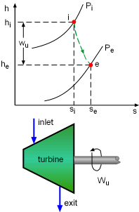 h-s Diagram of Adiabatic Turbine |
The second-law efficiencies for steady-flow devices like turbines, compressors, heat exchangers, and mixing chambers can be determined from their definitions. For a work-producing device such as turbine, the second-law efficiency is defined as where Wu is the actual useful work and Wrev is the reversible work. Wu can be obtained from the energy balance of the turbine. Usually the kinetic and potential energies associated with a fluid flowing through a turbine is neglectable compared with the enthalpy change of the fluid. In this case, the energy balance of the turbine is reduced to The reversible work can be determined by setting the exergy destruction to zero in the exergy balance relation. For one-inlet-one-exit steady-flow devices, such as turbines, it is, If the turbine is a adiabatic turbine, the reversible work equals the difference of the flow exergy at the inlet and the exit. Therefore, the second-law efficiency of an adiabatic turbine can be determined as |
|||||||||||||
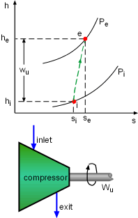 h-s Diagram of Adiabatic Compressor |
The second-law efficiency of a compressor can be determined using the similar method. It is |
|||||||||||||
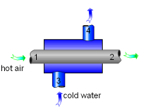 Heat Exchanger with Two Unmixed Fluid Stream |
Since no work is involved in heat exchangers and mixing chambers, their second-law efficiencies are defined as the ratio of exergy recovered to exergy supplied. A heat exchanger with two unmixed fluid streams is shown on the left. Hot stream enters at state 1 and leaves ad state 2, cold stream enters at state 3 and leaves at state 4. During the heat exchange process, exergy supplied equals the exergy lost in the hot stream and exergy recovered equals the exergy gained in the cold stream. Thus, the second-law efficiency of a heat exchanger is |
|||||||||||||
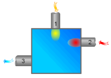 Adiabatic Mixing Chamber |
The second-law efficiency of a mixing chamber can be obtained using the similar method. |
|||||||||||||
|
||||||||||||||


