| Ch 10. Virtual Work & Potential Energy | Multimedia Engineering Statics | ||||||
|
Virtual Work |
Potential Energy | ||||||
| Virtual Work | Case Intro | Theory | Case Solution | Example |
| Chapter |
| 1. Basics |
| 2. Vectors |
| 3. Forces |
| 4. Moments |
| 5. Rigid Bodies |
| 6. Structures |
| 7. Centroids/Inertia |
| 8. Internal Loads |
| 9. Friction |
| 10. Work & Energy |
| Appendix |
| Basic Math |
| Units |
| Sections |
| Search |
| eBooks |
| Dynamics |
| Fluids |
| Math |
| Mechanics |
| Statics |
| Thermodynamics |
| Author(s): |
| Kurt Gramoll |
| ©Kurt Gramoll |
| STATICS- Example |
||
| Example |
||
|
|
A common mechanism that converts rotary motion into reciprocating motion or vice-versa is sometimes referred as a "Slider-crank mechanism", which is shown at the left. It has wide range of applications like pumps, engines, and compressors. Generally, the mechanism consists of two rigid links and a piston that are connected by frictionless joints and constrained to move in a single plane. The link AC is called a "crank-shaft" and the link CB is called a "connecting rod". The slider-crank mechanism has only one degree of freedom since the location of both links can be specified by the single independent coordinate θ In this case, the crank-shaft, AC, weighs 20 N and connecting rod, CB, weighs 35 N. The weight of the links pushes the piston towards right. To keep this system in equilibrium, a force, F, of 70 N pushes in the opposite direction. Determine angle θ for the equilibrium of the slider-crank mechanism. |
|
| Solution |
||
| To solve for the equilibrium angle θ, the principle of virtual work can be used. | ||
 Free-body Diagram of the Slider-crank Mechanism |
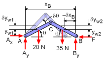
Begin with a free-body diagram of the slider-crank mechanism as shown at the left. If the origin is established at the fixed support A, the location of F and center of gravity for each link can be specified by the position coordinates xB, yW1, and yW2, respectively. Let point B undergoes a virtual displacement δxB in the negative x direction. The deflection is assumed to be small even though it is shown large in the diagram. Because point A is fixed, the reaction forces at A perform no work and By does not move in the direction of the force so no work is performed by By. |
|
Expressing the position coordinates of point B and center of gravity of links in terms of the independent coordinate θ and taking the derivatives to find virtual displacements yields, xB = 0.5 cosθ + 0.5 cosθ = 1 cosθ yW1 = 0.25 sinθ yW2 = 0.25 sinθ As shown in the free-body diagram, an increase in θ (i.e. δθ) causes a decrease in xB and an increase in yW1 and yW2 | ||
The total virtual work performed during the virtual displacement is the sum of the virtual work performed by the force F, and the virtual work performed by the weight of the connecting rod and crank-shaft, δU = 0 Putting results obtained earlier in the above equation gives, 20 (0.25) cosθ δθ + 35 (0.25) cosθ δθ (13.75 cosθ - 70 sinθ) δθ = 0 Noting that δθ can not be zero, θ = tan-1(13.75 / 70) = 11.11o Equilibrium of crank-shaft mechanism is obtained when crank-shaft is rotated by 11.11o in the anti-clockwise direction. | ||
Practice Homework and Test problems now available in the 'Eng Statics' mobile app
Includes over 500 free problems with complete detailed solutions.
Available at the Google Play Store and Apple App Store.
