| Ch 6. Structures | Multimedia Engineering Statics | ||||||
| 2-D Trusses: Joints | 2-D Trusses: Sections | 3-D Trusses | Frames and Machines | ||||
| 3-D Trusses/Space Trusses | Case Intro | Theory | Case Solution | Example |
| Chapter |
| 1. Basics |
| 2. Vectors |
| 3. Forces |
| 4. Moments |
| 5. Rigid Bodies |
| 6. Structures |
| 7. Centroids/Inertia |
| 8. Internal Loads |
| 9. Friction |
| 10. Work & Energy |
| Appendix |
| Basic Math |
| Units |
| Sections |
| eBooks |
| Dynamics |
| Fluids |
| Math |
| Mechanics |
| Statics |
| Thermodynamics |
| ©Kurt Gramoll |
|
|
||
|
|
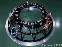
Since all members are symmetrical around the inter-stage structure, all members will have the same load. Using the method of joints, the forces at joint B on the bottom ring is analyzed by summing the forces, ΣFB = 0 The free-body diagram includes the external thrust load and all member forces acting at joint B. Since Joint B is in static equilibrium, the summation of all force vectors must equal zero. Since this is a 3D problem, all forces will be represented in the vector i, j, k format. The total thrust load of 2,400 kN is evenly distributed around the inter-stage structure so each joint will have to withstand a vertical load of 300 kN. FT = 300 k
Use the location of points B and E to define the unit directional vector of FBE. Ex = 0.75 sin22.5 = 0.2870 m Bx = 0 m BE = ((0.2870 - 0)2 + (-0.6929
- (-1))2 The vector FBE in i, j, k format is The member force FBD is similar to FBE except the x component is reversed. The magnitudes will be the same: FBD = FBE (-0.2645i + 0.2830j + 0.9217k) If forces are summed in the z direction, ΣFz = 0, only one unknown remains, FBE. Solving for FBE gives 2 FBE 0.9217 + 300 = 0 FBE = -162.7 kN compression |
|
Practice Homework and Test problems now available in the 'Eng Statics' mobile app
Includes over 500 free problems with complete detailed solutions.
Available at the Google Play Store and Apple App Store.