| Ch 9. Columns | Multimedia Engineering Mechanics | ||||||
|
Basic Columns |
Fixed Columns |
Eccentric Loads |
|||||
| Eccentric Loads & Secant Formula | Case Intro | Theory | Case Solution |
| Chapter |
| 1. Stress/Strain |
| 2. Torsion |
| 3. Beam Shr/Moment |
| 4. Beam Stresses |
| 5. Beam Deflections |
| 6. Beam-Advanced |
| 7. Stress Analysis |
| 8. Strain Analysis |
| 9. Columns |
| Appendix |
| Basic Math |
| Units |
| Basic Mechanics Eqs |
| Sections |
| Material Properties |
| Structural Shapes |
| Beam Equations |
| eBooks |
| Dynamics |
| Fluids |
| Math |
| Mechanics |
| Statics |
| Thermodynamics |
| ©Kurt Gramoll |
|
|
|||||
| Eccentric Axial Loads |
|||||
|
Generally, columns are designed so that the axial load is inline with the column. These types of columns were analyzed in the previous sections (Basic Columns and Fixed Columns). However, there are situations that the load will be off center and cause a bending in the column in addition to the compression. This type of loading is called eccentric load and is analyzed differently. For simplification, only pin-pin columns will be analyzed in this section for eccentric loading. Stresses for the other beam types (pin-fixed, fixed-fixed, and fixed-free) with eccentric loading can be determined by using the effective length concept. |
|||||
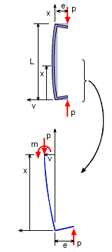 Column Deflection due to Eccentric Axial Load |
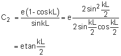
When a column is load off center, bending can be sever problem and may be more important than the compression stress or buckling. To better understand this, take an eccentrically loaded column and cut it at a distance x from the bottom pin as shown in the diagram on the left. The horizontal direction is labeled as v which represents the deflection of the column. At the cut surface, there will be both an internal moment, m, and the axial load P. This partial section of the column must still be equilibrium, and moments can be summed at the cut surface, giving, ΣM = 0 Recall, from beams, bending in a structure can be modeled as m = EI d2v/dx2, giving EI d2v/dx2 + Pv = -Pe This is a classical differential equation that can be solved using the general solution, v = C1 sin kx + C2 cos kx - e where k = (P/EI)0.5. The constants C1 and C2 can be determined using the boundary conditions. First, the deflection, v, at x = 0 is 0 giving 0 = C1 0 + C2 1 - e The second boundary condition specifies the deflection, v, at X = L is also 0, giving, 0 = e sin kL + C2 cos kL - e Now that the constants are known, the final deflection equation as a function of x is
Always remember, tan, sin and cos, are radians in this equation, not degrees. |
||||
|
Maximum Deflection |
||||
|
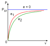
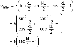
The maximum deflection occurs at the column center, x = L/2, since both ends are pinned. This gives, If the eccentricity is 0, then the deflection is 0 until the column buckles as shown in the diagram. For any non-zero value for e, then the deflection is gradual and then quickly grows as the load P increases. |
|||||
| Maximum Stress |
|||||
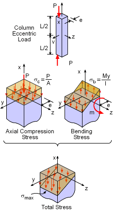 Eccentric Loaded Column Stress |
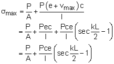
Unlike basic column buckling, eccentric loaded columns bend and must withstand both bending stresses and axial compression stresses. This can be illustrated by looking at both these stresses separately. The axial load P, will produce a compression stress P/A. Since the load P is not at the center, it will cause a bending stress My/I. The maximum compression stress will be total of both these stress, giving While generally compression stress is noted as negative, the maximum is considered an absolute value and thus positive. The c term is the largest distance from the neutral axis. The maximum moment, Mmax, is at the mid-point of the column (x = L/2), Mmax = P (e + vmax) Combining the above equations gives But I and A can be related using the radius of gyration, r, as I = Ar2. This gives the final form of the secant formula as
Again, remember, tan, sin and cos, are radians not degrees. Also, L is for a pin-pin column. For other column boundary conditions, Leffective can be used. |
||||
There is a lot of terms in the secant formula that may be confusing. The first issue is to understand what is unknown. Generally, the load P is not known for a given column, material type, and maximum allowable stress, σmax. One might ask, if P is the unknown, why is the equation not formulated with P on one side of the equation? The problem is P cannot be isolated on one side of the question since this is a nonlinear equation. Thus P cannot be solved using algebra but a numerical method is needed such as a root finder or even trial and error. |
|||||
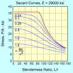 Secant Formula Curves for
 Various Stiffness Values |
So, back to the terms. The stress maximum, σmax, is generally the yield stress or allowable stress of the column material, which is known. The geometry of the column, length L, area A, radius of gyration r, and maximum distance from the neutral axis c are also known. The eccentricity, e, and material stiffness, E, are considered known. The secant formula can be better understood if it is plotted as function of the slenderness ration, L/r and the pure axial compression stress, P/A. The stiffness, E, maximum stress, σmax, and eccentricity ratio, ec/r2, need to be set. In the diagram, the σmax, is set at 36 ksi and the eccentricity ratio is shown for various values. For the eccentricity ratio of 0, the Euler equation is recovered and is shown on the graph as the red curve. |
||||
Practice Homework and Test problems now available in the 'Eng Mechanics' mobile app
Includes over 500 free problems with complete detailed solutions.
Available at the Google Play Store and Apple App Store.

