| Ch 9. Columns | Multimedia Engineering Mechanics | ||||||
|
Basic Columns |
Fixed Columns |
Eccentric Loads |
|||||
| Fixed Columns | Case Intro | Theory | Case Solution | Example |
| Chapter |
| 1. Stress/Strain |
| 2. Torsion |
| 3. Beam Shr/Moment |
| 4. Beam Stresses |
| 5. Beam Deflections |
| 6. Beam-Advanced |
| 7. Stress Analysis |
| 8. Strain Analysis |
| 9. Columns |
| Appendix |
| Basic Math |
| Units |
| Basic Mechanics Eqs |
| Sections |
| Material Properties |
| Structural Shapes |
| Beam Equations |
| eBooks |
| Dynamics |
| Fluids |
| Math |
| Mechanics |
| Statics |
| Thermodynamics |
| ©Kurt Gramoll |
|
|
|||||||||||||||||||||||||||||||||||||||||||||||||||||||||||||||||||||||||||||||||||||||||||||||||
|
|
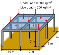
This case requires the center column for a basic building be designed to carry the roof load. The roof load has a dead and live roof load of, 300 and 250 kg/m2, respectively. Generally, a dead load is the static, non-changing load such as roof weight and equipment on the roof. On the other hand, a live load is changing loads, such as snow or wind. The total (worst case) should be considered when designing the column. The other major condition is that the selection of the center column needs to be specified from a group of I-beams that are in storage. The best column will be the lightest column that can withstand the roof load. Both buckling and compression failure should be checked. |
||||||||||||||||||||||||||||||||||||||||||||||||||||||||||||||||||||||||||||||||||||||||||||||||
| Center Column Load |
|||||||||||||||||||||||||||||||||||||||||||||||||||||||||||||||||||||||||||||||||||||||||||||||||
|
|
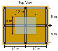
The center column will need to carry the roof load that is half way to each of the other columns. The total roof area carried by the center column is 10 m by 8 m as shown in the diagram at the left. The total roof load over this area is F = (10 m)(8 m)(300 + 250 kg/m2)(9.81 m/s2) = 431.6 kN The last term is the standard gravitational constant. The column requires a factor of safety of 2.5, so the design load needs to be increased by a factor of 2.5, giving Pcr = 2.5 (431.6 kN) = 1.079 MN |
||||||||||||||||||||||||||||||||||||||||||||||||||||||||||||||||||||||||||||||||||||||||||||||||
| Required Moment of Inertia |
|||||||||||||||||||||||||||||||||||||||||||||||||||||||||||||||||||||||||||||||||||||||||||||||||
|
|
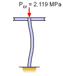
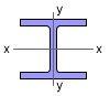
The minimum moment of inertia is needed so that a suitable wide-flange I-beam can be chosen. Since both ends are assumed to be fixed, the Euler buckling equation is Substituting known values give, Solving for the moment of inertia, I = 6.696 × 10⁻⁶ m4 = 6.696 × 106 mm4 The I-beam must have this moment of inertia (or greater) in both direction. Generally, I-beams have a higher inertia around the x-axis, but buckling can occur about either axis. |
||||||||||||||||||||||||||||||||||||||||||||||||||||||||||||||||||||||||||||||||||||||||||||||||
| Column Selection |
|||||||||||||||||||||||||||||||||||||||||||||||||||||||||||||||||||||||||||||||||||||||||||||||||
|
There are currently 18 different wide-flange I-beams available for the construction of the building. They are list below. |
|||||||||||||||||||||||||||||||||||||||||||||||||||||||||||||||||||||||||||||||||||||||||||||||||
Wide-Flange Beams Available |
|||||||||||||||||||||||||||||||||||||||||||||||||||||||||||||||||||||||||||||||||||||||||||||||||
|
Both Ix and Iy must be at least 6.696 × 106 mm4 to satisfy the buckling requirements. The critical moment of inertia is Iy. There are several beams that have moment of inertia's greater than 6.696 in both directions. However, the lightest one is W200 x 36 |
|||||||||||||||||||||||||||||||||||||||||||||||||||||||||||||||||||||||||||||||||||||||||||||||||
| Compression Stress Check |
|||||||||||||||||||||||||||||||||||||||||||||||||||||||||||||||||||||||||||||||||||||||||||||||||
|
Even though the column was designed assuming buckling, the compression stress should be checked to make sure it does not exceed the yield stress of the material. The compression stress is σ = P/A = (1.079 MN)/(4,570 mm2) = 236.1 MPa This is less than the yield stress of 250 MPa for structural steel and will not yield in compression. |
|||||||||||||||||||||||||||||||||||||||||||||||||||||||||||||||||||||||||||||||||||||||||||||||||
Practice Homework and Test problems now available in the 'Eng Mechanics' mobile app
Includes over 500 free problems with complete detailed solutions.
Available at the Google Play Store and Apple App Store.