| Ch 7. Stress Analysis | Multimedia Engineering Mechanics | ||||||
|
Plane Stress |
Principal Stresses |
Mohr's Circle for Stress |
Failure |
Pressure Vessels |
|||
| Failure | Case Intro | Theory | Case Solution | Example |
| Chapter |
| 1. Stress/Strain |
| 2. Torsion |
| 3. Beam Shr/Moment |
| 4. Beam Stresses |
| 5. Beam Deflections |
| 6. Beam-Advanced |
| 7. Stress Analysis |
| 8. Strain Analysis |
| 9. Columns |
| Appendix |
| Basic Math |
| Units |
| Basic Mechanics Eqs |
| Sections |
| Material Properties |
| Structural Shapes |
| Beam Equations |
| eBooks |
| Dynamics |
| Fluids |
| Math |
| Mechanics |
| Statics |
| Thermodynamics |
| ©Kurt Gramoll |
|
|
||
|
|
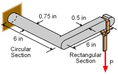
The load that can be safely carried by a bracket needs to be determined. The bracket is made from standard steel with a yield stress of 36 ksi. Since there are both bending stress and torsional shear stress in the circular bar section, the stress state will not be uniaxial. This will require the use of the stress transformation equations to find the principal stresses. With the principal stresses, the maximum distortion energy failure criteria can be applied, and the total allowable load, P, can be determined. For safety, a factor of safety of 2 is required. Thus, the bracket stress should not exceed 36/2 = 18 ksi. It is assumed that the maximum torsional shear stresses and bending stresses will occur in the circular section at the wall. |
|
| Torsional Shear Stress |
||
 Equivalent Torque in the Circular Section due to the Force P in the Rectangular Section |
The load P will cause a bending moment at the joint between the circular and rectangular sections. The equivalent moment or torque, T, at the joint will be T = (6 in) P This torque will cause a constant twist in the circular section which will produce a torsional shear stress, |
|
| Bending Stress |
||
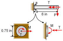 Bending Moment M and Twisting Torque T at Wall |
The load P will cause the bracket to bend in two directions. The first will be about the circular section, but there is no torsional stress in this section. Second, there will be a moment reaction at the wall that will bend the circular cross section. This moment, M, is shown in the diagram at the left and is equals to M = (6 in) P The bending stress will be, |
|
| Combined Stress State |
||
|
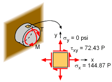
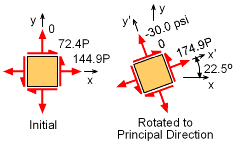
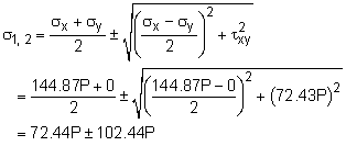
Both the torsional moment, T and the bending moment M, cause shear and bending normal stresses, respectively. If an element at the top of the circular section is analyzed as shown in the diagram, the stress state would be σx = 144.87 P τxy = 72.43 P The principal stresses will be
σ1 = 174.88 P and σ2 = -30.00 P |
|
| Maximum Distortion Energy Criteria |
||
|
|
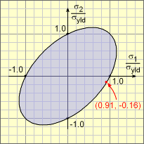
Now that the principal stresses are known in terms of the load P, the failure criteria can be applied. For the maximum distortion energy criteria, the following relationship must be meet, Substituting the principal stresses and yield stress (do not forget the factor of safety), gives (174.88P)2 + (-30.00P)2 Solving for P, gives P = 93.91 lb The final principal stresses are σ1 = 174.88 P = 16.42 ksi σ2 = -30.00 P = -2.82 ksi These principal normal stresses can be normalized with the design stress, 18 ksi, to give σ1/σdesign = 16.42/18 = 0.9122 σ2/σdesign = -2.82/18 = -0.1567 This point are plotted on the failure envelop diagram at the left. |
|
Practice Homework and Test problems now available in the 'Eng Mechanics' mobile app
Includes over 500 free problems with complete detailed solutions.
Available at the Google Play Store and Apple App Store.
