| Ch 5. Beam Deflections | Multimedia Engineering Mechanics | ||||||
|
Integration of Moment |
Integration of Load |
Method of Superposition |
Indeterminate Beams |
||||
| Integration of Moment Equation | Case Intro | Theory | Case Solution | Example |
| Chapter |
| 1. Stress/Strain |
| 2. Torsion |
| 3. Beam Shr/Moment |
| 4. Beam Stresses |
| 5. Beam Deflections |
| 6. Beam-Advanced |
| 7. Stress Analysis |
| 8. Strain Analysis |
| 9. Columns |
| Appendix |
| Basic Math |
| Units |
| Basic Mechanics Eqs |
| Sections |
| Material Properties |
| Structural Shapes |
| Beam Equations |
| eBooks |
| Dynamics |
| Fluids |
| Math |
| Mechanics |
| Statics |
| Thermodynamics |
| ©Kurt Gramoll |
|
|
||
|
|
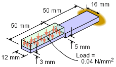
The deflection at the beam tip can be determined by first finding the moment equations and then integrating those equations. There are actually two moment equations, one for each half, since the load and beam structure is not continuous. Four boundary conditions will be needed, two for each beam section. |
|
| Moment Equation and Diagram |
||
|
|
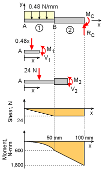
One method to determine beam deflections is to integrate the moment equation. This requires that the moment equation is known before starting the integration. This can be done by cutting each beam section and developing a moment equation as a function of the beam location, x (details for this process can be found in the Shear and Moment Diagrams section). For the cantilever beam, there are two sections. The first one is from point A to B. The second is from point B to C. Making a cut in the first sections and solving for the moment and shear at the cut surface gives, V1 = -0.48x N M1 = -0.24x2 N-mm The second cut in section 2 gives V2 = -24.0 N M2 = -24 (x - 25) N-mm = -24x + 600 N-mm The equations are plotted at the left. |
|
| Beam Properties |
||
|
|
The moment of inertia for a rectangular cross section gives, I1 = 12(3)3/12 = 27.0 mm4 I2 = 16(5)3/12 = 166.7 mm4 The material stiffness, E, is given as E = 200 GPa = 200×109 N/m2 (1 m/1000 mm)2 = 200,000 N/mm2 |
|
| Integrating Moment Equations |
||
|
The deflection of any beam can be found by integrating the basic moment differential equation, EIv´´ = M However, each section must be integrated separately. Integrating section AB twice gives, Recall, v is the deflection and v´ is the slope of the beam. The constants of integration, C1 and C2, must be determined from the boundary conditions (see below). Integrating the second beam section BC, gives |
||
| Boundary Conditions |
||
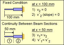 Four Boundary Conditions |
There are four constants of integrating that need to be defined. This requires four boundary conditions. The first two conditions are due to the fixed joint at the right end. This requires both the deflections, v, and the slope, v´, to be zero. These are listed in the table at the left as conditions 1) and 2). Another two conditions can be identified at the joint between beam sections 1 and 2. Since the beam is continuous, the beam deflection and slope on either side of the joint must be equal. This gives the third and fourth condition, as listed in the table. |
|
| Determining Constants |
||
|
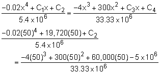
With the four boundary conditions defined, four equations can now be constructed which will allow all four constants to be determined. Generally, boundary conditions can be applied so that only one constant is present in a given equation. However, sometimes two or three equations will need to be solved simultaneously. Boundary Condition 2) v´2 = 0 at x = 100 mm
Boundary Condition 1) v2 = 0 at x = 100 mm Boundary Condition 4) v´1 = v´2 at x
= 50 mm Boundary Condition 3) v1 = v2 at x =
50 mm |
||
| Final Deflection Equations |
||
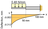 Final Deflection Curve |
The final deflection equations for both beam sections are v1 = -3.704×10-9x4 +
0.003652x - 0.2120 mm v2 = -1.2×10-7x3 +
9.0×10-6x2 + 0.0018x
- 0.15 mm The maximum deflection at the tip (x = 0) is vx=0 = -0.2120 mm |
|
Practice Homework and Test problems now available in the 'Eng Mechanics' mobile app
Includes over 500 free problems with complete detailed solutions.
Available at the Google Play Store and Apple App Store.
