| Ch 10. Open-Channel Flow | Multimedia Engineering Fluids | ||||||
|
Uniform Flow |
Gradually Varied Flow |
Rapidly Varied Flow |
|||||
| Rapidly Varied Flow | Case Intro | Theory | Case Solution | Example |
| Chapter |
| 1. Basics |
| 2. Fluid Statics |
| 3. Kinematics |
| 4. Laws (Integral) |
| 5. Laws (Diff.) |
| 6. Modeling/Similitude |
| 7. Inviscid |
| 8. Viscous |
| 9. External Flow |
| 10. Open-Channel |
| Appendix |
| Basic Math |
| Units |
| Basic Fluid Eqs |
| Water/Air Tables |
| Sections |
| eBooks |
| Dynamics |
| Fluids |
| Math |
| Mechanics |
| Statics |
| Thermodynamics |
| ©Kurt Gramoll |
| |
||
Rapidly varied flow is another type of nonuniform
open-channel flow where the fluid depth changes rapidly over a small
reach of the channel. The phenomenon of a hydraulic jump, one type of
rapidly varied flow, will be presented first, followed by a discussion
of the specific force. A brief discussion of a sharp-crested weir is
given at the end of this section. |
||
| Hydraulic Jump |
||
|
|
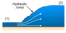
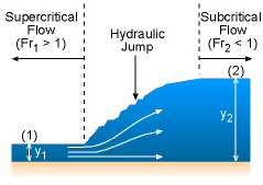
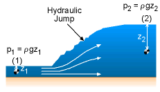
Hydraulic jumps occur when the flow changes suddenly from supercritical to subcritical flow. This process is often accompanied by extreme turbulence and high energy losses. Hydraulic jumps often occur when there is a conflict between the upstream and downstream controls. It is the water equivalent of a sonic boom. To describe the jump condition, consider the hydraulic jump shown in the figure. The shear stress at the bottom of the channel is assumed to be negligible. It is also further assumed that the two ends of the control volume (indicated by red dashed lines) are far away from the jump such that the flow is uniform, steady and one-dimensional. Applying the momentum equation to the control volume in the flow direction yields: -ρV12A1 + ρV22A2 = p1A1 - p2A2 [1] where V and A denote the average velocity and cross sectional area, respectively. The pressures at both sections are hydrostatic, the net force due to these is simply the pressure at the centroid times the cross-sectional area. That is, p1 = ρgz1 and p2 = ρgz2 [2] where z is the distance from the water surface to the centroid of the cross-sectional area. The average velocity can be expressed in terms of the volumetric flow rate as V1 = Q/A1 and V2 = Q/A2 [3] Combining Eqns. [1] through [3], and rearranging terms yields Q2/gA1 + z1A1 = Q2/gA2 + z2A2 [4] Basically, Eqn. 4 indicates that the momentum function (Q2/gA + zA) at both sections are the same. The concept of the momentum function will be discussed further in this section. |
|
For a rectangular channel with a width of b (A = by, Q = Vby and z = y/2), the momentum equation (Eqn. 4) becomes From the continuity equation Q = V1by1 = V2by2 where Fr1 is the upstream Froude number, and is given by The solution with the minus sign yields a negative water depth ratio y1/y2, hence this solution is not physically possible. Thus, is the relation to describe the upstream and downstream water depths of a hydraulic jump in a rectangular channel. |
||
| Specific Force (Momentum Function) |
||
 Specific Force Diagram |
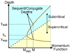
Similar to the concept of specific energy, the specific force or the momentum function (M) can be defined as: A specific force diagram plots the specific force as a function of the channel depth (y versus M). The minimum momentum function (Mmin) corresponds to critical flow (i.e., Fr = 1), and the corresponding channel depth is referred to as the critical depth (yc). For a given momentum function, two different channel depths (ysub and ysup) are possible, and they are referred to as the sequent or conjugate depths. The top and bottom portions of the specific force curve correspond to subcritical and supercritical flows, respectively. |
|
| Sharp-Crested Weir |
||
|
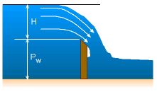
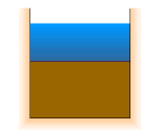
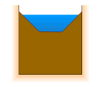
| A weir is an obstruction in an open-channel that can be used to determine the flow rate. Basically, a sharp-crested weir is a vertical plate with sharp edges placed across the channel. Different shapes of weirs (e.g., rectangular, triangular, and trapezoidal) are shown in the figures. The weir discharge can be derived from Bernoulli's equation. The details of the derivation process are omitted for brevity. The volumetric flow rate for a rectangular weir is given by where L is the width of the weir, and H is the head of the weir (see figure). As expected, the actual flow rate deviates from that obtained from theory (Eqn. 10). Hence, an experimentally-determined discharge coefficient is introduced to correct the flow rate: Cd = 0.611 + 0.075 (H/Pw) [12] where Pw is the height of the weir above the channel bed, as shown in the figure. Similar expressions for determining the flow rate of triangular and trapezoidal weirs can be derived, and discharge coefficients are available for various shapes of the weirs. For more information, students are referred handbooks on hydraulics. [ *Reference: Henderson, F. M., "Open Channel Flow," Macmillan, New York, 1966.] |
|
Practice Homework and Test problems now available in the 'Eng Fluids' mobile app
Includes over 250 free problems with complete detailed solutions.
Available at the Google Play Store and Apple App Store.
 [6]
[6]
 [7]
[7] 