| Ch 7. Incompressible and Inviscid Flow | Multimedia Engineering Fluids | ||||||
|
Bernoulli's Equation |
Flow Measurements |
Superposition of Flows |
Flow around Cylinder |
||||
| Flow Measurements | Case Intro | Theory | Case Solution |
| Chapter |
| 1. Basics |
| 2. Fluid Statics |
| 3. Kinematics |
| 4. Laws (Integral) |
| 5. Laws (Diff.) |
| 6. Modeling/Similitude |
| 7. Inviscid |
| 8. Viscous |
| 9. External Flow |
| 10. Open-Channel |
| Appendix |
| Basic Math |
| Units |
| Basic Fluid Eqs |
| Water/Air Tables |
| Sections |
| eBooks |
| Dynamics |
| Fluids |
| Math |
| Mechanics |
| Statics |
| Thermodynamics |
| ©Kurt Gramoll |
| |
||
| Flow meters are encountered frequently in our daily lives (e.g., water meters in our homes and gasoline meters at the gas stations). Several common flow measurement methods for pipe flow will be presented in this section. Flow measurement methods, such as the sluice gate and the sharp crested weir will be presented in the later section (open-channel). | ||
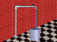 Simple Flowrate Measurement Technique |
||
| Simple Flowrate Measurement Technique |
||
| The simplest technique to determine the steady flow
rate of a liquid is to measure the amount of liquid collected over a period
of time. For example,one could collect the liquid in a container of known
size. If the time needed to fill the container is recorded, then the flow
rate can be easily determined from the equation Q = Volume/Time |
||
| Rotameters |
||
|
|
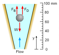
A common device used to measure volumetric flow rate is the rotameter. The rotameter consists of a transparent tapered tube with a float in it. When the flow enters the rotameter, the float will rise to a position where both the drag force and buoyant force will be balanced by its own weight. That is, FD + FB = W
Solving for flow velocity, um,gives, Note that um is the mean velocity passing through the annular space between the float and the tube; Vb is the volume of the float; ρb and ρf are the density of the float and fluid, respectively; CD is the drag coefficient; Afr is the projected area of the float; and g is the acceleration of gravity. The volumetric flow rate is then given by Q = umAm where Am is the area of the annular space. The discussion of rotameters has taken into account the drag force, which is due to viscous effects. Although this chapter is mainly focused on discussion of incompressible and inviscid flow, for illustration purposes, it is appropriate to introduce the flow measurement technique using the rotameter here, which includes viscous drag effect (modeled as CD). |
|
| Orifices, Nozzles and Venturi Meters |
||
|
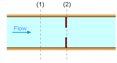
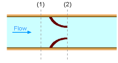
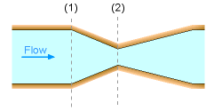
Another method to measure flow is by means of a flow obstruction. Examples of this method include orifices, nozzles and venturi meters. All of these methods are developed based on Bernoulli's equation, hence the fluid flow is assumed to be steady, incompressible and inviscid. Bernoulli's equation can be applied between point 1 and 2 for any of the diagram shown on the left. This gives, If the change in the elevation is negligible then the velocity at point 2 is If the flow is steady and incompressible at both points 1 and 2, the continuity equation gives Q = A1V1 = A2V2 Combining the above two equations yields Note that the analysis thus far is based on the assumption that the fluid is inviscid. However, friction losses due to viscosity are unavoidable in real engineering practice, hence the actual flow rate would always be smaller than the flow rate given in the above equation. In practice this deviation from theory is corrected with a discharge coefficient. |
|
Practice Homework and Test problems now available in the 'Eng Fluids' mobile app
Includes over 250 free problems with complete detailed solutions.
Available at the Google Play Store and Apple App Store.
