| Ch 8. Internal Loads | Multimedia Engineering Statics | ||||||
|
Int. Forces and Moments |
V and M Diagrams I | V and M Diagrams II | V, M, Load Relationships | ||||
| Shear and Moment Diagrams II | Case Intro | Theory | Case Solution |
| Chapter |
| 1. Basics |
| 2. Vectors |
| 3. Forces |
| 4. Moments |
| 5. Rigid Bodies |
| 6. Structures |
| 7. Centroids/Inertia |
| 8. Internal Loads |
| 9. Friction |
| 10. Work & Energy |
| Appendix |
| Basic Math |
| Units |
| Sections |
| eBooks |
| Dynamics |
| Fluids |
| Math |
| Mechanics |
| Statics |
| Thermodynamics |
| ©Kurt Gramoll |
| |
||
 Wing Modeled as a Cantilever Beam - Force Diagram |
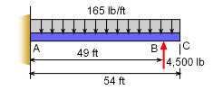
The wing can be modeled as a simple cantilevered beam with a distributed load of 165 lb/ft and point force load of 4,500 lb. The first step in solving this problem is to determine the reaction force and moment at the fixed end, A. This can be done more efficiently by replacing the distributed load with a point load of magnitude Wr at location xr. |
|
 Wing Model as Cantilever Beam |
The location of the point load will be |
|
 Wing Free Body Diagram |
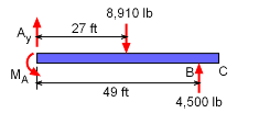
With a free-body diagram (shown at left) the reaction force and moment can be determined.
ΣFy = 0 ΣMA = 0 There will be two sets of shear and moment equations, one to the left of F and one to the right. |
|
| Section 1 (0 ≤ x ≤ 49) |
||
|
|
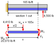
After making the section cut, and developing a free-body diagram for the left side of the wing, sum the forces to get the shear equation. ΣFy = 0 Summing the moments give the moment equation, ΣMcut = 0 |
|
| Section 2 (49≤ x ≤ 54) |
||
|
|
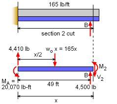
Once again, first make a cut in section 2 (left of point B). Next, construct a free-body diagram and then sum forces to get the shear equation. ΣFy = 0 Summing the moments give the moment equation, ΣMcut = 0 |
|
 Shear and Moment Diagrams |
Maximum Internal Shear |
|
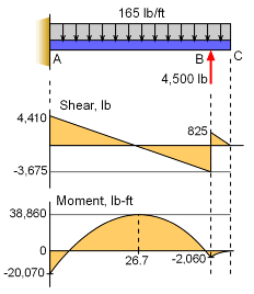
| The shear equations for both sections can now be plotted to help identify the maximum and their locations. Both shear equations are linear lines, and shown at the left. The maximum shear occurs at the far left where the wing is fixed to the aircraft body. The magnitude is 4,410 lb. |
||
| Maximum Internal Moment |
||
| Like the shear, the two moment equations can be plotted to help identify the maximum internal moment. However, since the equations are quadratic curves, they are more difficult to plot than the linear lines for the shear. There are a few techniques that can assist in plotting curves. If the second derivative is positive, then the curve is facing upward. For both equations, their second derivatives are negative, so the they face downward. The maximum can be determined by equating the first derivative to zero. For the first section equation, that becomes, d(M1)/dx = -165x + 4,410 = 0 x = 26.73 ft The maximum value at 26.73 ft is M26.73 = -82.5(26.73)2 + 4,410(26.73) - 20,070 Mmax = 38,860 lb-ft |
||
Practice Homework and Test problems now available in the 'Eng Statics' mobile app
Includes over 500 free problems with complete detailed solutions.
Available at the Google Play Store and Apple App Store.

