| Ch 6. Structures | Multimedia Engineering Statics | ||||||
| 2-D Trusses: Joints | 2-D Trusses: Sections | 3-D Trusses | Frames and Machines | ||||
| 2-D Trusses: Method of Joints | Case Intro | Theory | Case Solution | Example |
| Chapter |
| 1. Basics |
| 2. Vectors |
| 3. Forces |
| 4. Moments |
| 5. Rigid Bodies |
| 6. Structures |
| 7. Centroids/Inertia |
| 8. Internal Loads |
| 9. Friction |
| 10. Work & Energy |
| Appendix |
| Basic Math |
| Units |
| Sections |
| eBooks |
| Dynamics |
| Fluids |
| Math |
| Mechanics |
| Statics |
| Thermodynamics |
| ©Kurt Gramoll |
|
|
||
| Support |
||
 Free Body Diagram (FBD) of Truss |
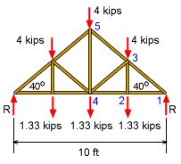
When solving any truss, the reaction forces at each support should be determined before trying to calculate individual member loads. Starting with a FBD of the entire truss, the basic moment equilibrium equation gives, ΣM1 = 0 Due to symmetry, the reaction forces at both the left and right wall are equal, RL = RR = R = 8 kips |
|
| Joint 1 |
||
 Joint 1 |
With the reactions known, it is now possible to analyze joint 1. Note that both F31 and F21 are drawn away from the joint, representing tension. The two unknowns forces, F31 and F21, can be found using the two force equilibrium equations, ΣFx
= 0 ΣFy
= 0 Substituting known values and solving gives, F31 = -8/sin40 = -12.45 kips |
|
| Joint 2 |
||
 Joint 2 |
The value of F21, 9.534 kips, was determined at joint 1 and can now be used at joint 2. The force in member F32 is easy to determine since all members and loads are perpendicular. Summing the forces in the vertical gives, ΣFy
= 0
Since there are only two horizontal member forces, they must be equal, ΣFx
= 0 |
|
| Joint 3 |
||
 Joint 3 |
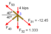
The value of F31, -12.45 kips, and F32, 1.333 kips, were determined from joint 1 and joint 2, respectively. It is now possible to determine forces, F53 and F43, at joint 3, ΣFx
= 0 = cos40 [-F53 - F43 + (-12.45)] ΣFy = 0 = sin40 [F53 - F43 - (-12.45)] - 4 - 1.333 Eliminating F53 gives, 0 = -2F43 - 4/sin40
- 1.333/sin40 and F53 = 4.148 - 12.45 = -8.302 kips |
|
| Joint 4 |
||
 Joint 4 |
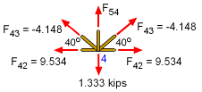
Now that F42, 9.534 kips, and F43, -4.148 kips, are known, joint 4 can be analyzed. Due to symmetry, the left member forces are the same as the right member forces. There is only one unknown force, F54. Using ΣFy = 0 gives, F54 + 2(-4.148) sin40 - 1.333 = 0
|
|
| Summary |
||
 Final Loads (kips) in Truss Members |
As shown by the force diagram, the largest tensile force is 9.534 kips and the largest compressive force is -12.45 kips. The best truss angle, θ, that minimizes the member loads can be determined by using the truss simulation. The best angle is the largest angle possible in the simulator, 65o. Thus a steep truss reduces the load. However, the cost is higher and buckling problems will also need to be considered. |
|
Practice Homework and Test problems now available in the 'Eng Statics' mobile app
Includes over 500 free problems with complete detailed solutions.
Available at the Google Play Store and Apple App Store.