| Ch 3. Forces & Particle Equilibrium | Multimedia Engineering Statics | ||||||
|
Equilibrium and FBD |
2-D Forces |
3-D Forces |
|||||
| Equilibrium & Free Body Diagrams | Case Intro | Theory | Case Solution | Example |
| Chapter |
| 1. Basics |
| 2. Vectors |
| 3. Forces |
| 4. Moments |
| 5. Rigid Bodies |
| 6. Structures |
| 7. Centroids/Inertia |
| 8. Internal Loads |
| 9. Friction |
| 10. Work & Energy |
| Appendix |
| Basic Math |
| Units |
| Sections |
| eBooks |
| Dynamics |
| Fluids |
| Math |
| Mechanics |
| Statics |
| Thermodynamics |
| ©Kurt Gramoll |
|
|
||
| Drawing FBD's |
||
 Free Body Diagram Example |
A Free-body diagram (FBD) is an essential tool when the forces on an object need to be determined using equilibrium equations. They help focus attention on the object of interest in order to determine the forces acting on it. Creating FBD's is a straightforward process:
|
|
| Coordinate System |
||
| The coordinate system is arbitrary when constructing a free-body diagrams. However, it is best to choose a coordinate system that will simplify future calculations. This may be done before or after making the diagram. |
||
 Forces Due to Rope/Cables |
Equilibrium |
|
|
An object is in equilibrium when each point inside the object has the same constant velocity (generally, velocity is zero for static's problems). Therefore, an object in equilibrium is not experiencing any accelerations, so Newton's 2nd Law can be written as ΣF = ma = 0 The vector sum of the external forces acting on an object in equilibrium is zero. |
||
| Representation of Forces |
||
|
|
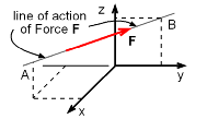
A force acts through a line of action, which is a vector representation of a force's magnitude and direction. On a rigid body, the force can be applied to any point on the object along the line of action of the force. Forces may be either internal (such as the force of a piston in an engine) or external (such as the force of a baseball bat against the ball). They may also act across the object's surface or at any point in its body. The force of gravity is an important factor when significant masses are involved. The weight of an object in a gravitational field can be expressed |W| = mg |
|
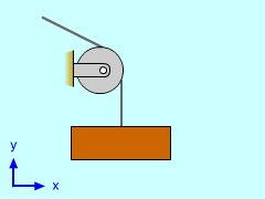 Forces Due to Pulley |
where m is the object's mass and g is the gravitational constant (g = 9.81 m/s2 = 32.2 ft/s2 on Earth's surface). Ropes and cables exert tension forces that only pull on an object and are therefore always represented as forces that are directed away from the object. Unless stated otherwise, we will always assume that ropes and cables are straight and their force is constant along the length. A pulley serves to change the direction of the force of a rope/cable, but the tension will be the same on both sides if we assume a mass-less pulley (not true in dynamic problems). |
|
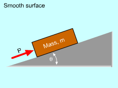
Contact forces result from contact between the surfaces of two objects. A contact force can usually be split into two components: a normal force perpendicular to the plane of contact and a frictional force parallel to the plane of contact. Frictional forces, however, can be neglected if the surface is smooth. Springs exert contact forces in a mechanical device. The force can be represented as |F| = k |L - Lo| where, k is the spring constant, L is the length after deflection, and Lo is the length before deflection. The use of springs when modeling complicated real-world structures is a useful tool. |
||
Practice Homework and Test problems now available in the 'Eng Statics' mobile app
Includes over 500 free problems with complete detailed solutions.
Available at the Google Play Store and Apple App Store.