| Ch 6. Advanced Beams | Multimedia Engineering Mechanics | ||||||
|
Composite Beams |
Unsymmetric Bending |
||||||
| Composite Beams | Case Intro | Theory | Case Solution | Example |
| Chapter |
| 1. Stress/Strain |
| 2. Torsion |
| 3. Beam Shr/Moment |
| 4. Beam Stresses |
| 5. Beam Deflections |
| 6. Beam-Advanced |
| 7. Stress Analysis |
| 8. Strain Analysis |
| 9. Columns |
| Appendix |
| Basic Math |
| Units |
| Basic Mechanics Eqs |
| Sections |
| Material Properties |
| Structural Shapes |
| Beam Equations |
| eBooks |
| Dynamics |
| Fluids |
| Math |
| Mechanics |
| Statics |
| Thermodynamics |
| ©Kurt Gramoll |
|
|
||
|
|
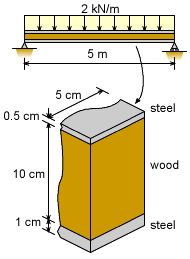
The ceiling beam is composed of three parts, two steel plates and a wood member. The plates are rigidly attached to the top and bottom surface of the wood member as shown in the diagram at the left. The beam must support a continuous load of 2 kN/m over a simple support span of 5 m. The beam is a composite beam of only two materials even though there are three sections. The wood will be treated as one material and the two plates will be treated as a single material with two areas. The first issue is to find the actual maximum moment. This is needed for the composite beam bending stress equations. Next, the neutral axis needs to be determined. From there, the actual moment of inertia for each material can be found. |
|
|
|
Maximum Moment |
|
|
|
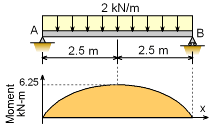
To determine the maximum bending stress, the maximum bending moment is needed. This moment is not a function of the cross section and can be determined by the moment diagram. This is a common beam loading and the maximum moment is at the center. Cutting the beam at the center and summing the moments gives ΣM = 0 M - 5 (2.5) + 2 (2.5) (2.5/2) = 0 M = 6,250 N-m |
|
| Neutral Axis |
||
|
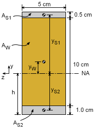
The location of the neutral axis (NA) is one of the most critical steps when solving for bending stresses in composite beams. Both the moment of inertia and the distance to the outside edge of both materials require knowing where the NA is located. |
||
 Beam Cross Section |
The NA can be determined from the equation 0 = EW QW + ES QS The steel section consists of two parts, 1 and 2, giving, 0 = EW (yW AW) + ES [(yS1 AS1) + (yS2 AS2)] = 12 (5 + 1 - h) (5) (10) +
= 3,600 - 600h + 5,625 - 500h + 500 - 1000h 9,725 = 2,100 h h = 4.631 cm Now that the distance h is known, the location of all material area centroids from the NA can be found. yW = 5 + 1 - 4.631 = 1.369 cm yS1 = 10 + 1 + 0.5 - 0.25 - 4.631 = 6.619 cm yS2 = - 4.631 + 0.5 = -4.131 cm |
|
| Moment of Inertia for Each Material |
||
|
|
With the neutral axis (NA) located, the moment of inertia about the NA for each of the two material areas can be calculated. Using the basic formula for the moment of inertia of rectangular areas, and the parallel axis theorem, gives, IW = h3 b / 12 + yW2 AW IS = IS1 + IS2 |
|
| Maximum Bending Stress |
||
|
The bending stress in each of the material areas can now be determined by using the bending stress equations for a two-material composite beam. There are two equations since each material section has different stress. |
||
 Beam Cross Section |
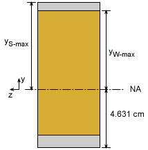
The y distance is the maximum distance from the neutral axis for each material section. yW-max = (10 + 1 + 0.5) - (0.5 + 4.631) = 6.369 cm yS-max = (10 + 1 + 0.5) - 4.631 = 6.869 cm Substituting values into both stress equations give, The beam will fail, even though the bending stress in the wood is below the wood failure stress of 50 MPa since the maximum bending stress in the steel is over 150 MPa. If the beam was only wood, it would still fail since the maximum bending stress would be 75 MPa (calculations not shown) which is beyond the failure stress of 50 MPa. |
|
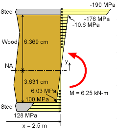 Bending Stress Through Beam at Center of Beam Span |
||
| Bending Stress Distribution |
||
| To better understand visually how the bending stress varies across the beam, it has been plotted at the left. Notice that the bending stress jumps at the interface between the materials. This is due to the jump in material stiffness (Young's modulus). On the other hand, the strain does not jump and is continuous from the top to the bottom. | ||
Practice Homework and Test problems now available in the 'Eng Mechanics' mobile app
Includes over 500 free problems with complete detailed solutions.
Available at the Google Play Store and Apple App Store.
