| Ch 4. Beam Stresses | Multimedia Engineering Mechanics | ||||||
|
Bending Strain and Stress |
Beam Design |
Shear Stress |
Built-up Beams |
||||
| Shear Stress | Case Intro | Theory | Case Solution | Example |
| Chapter |
| 1. Stress/Strain |
| 2. Torsion |
| 3. Beam Shr/Moment |
| 4. Beam Stresses |
| 5. Beam Deflections |
| 6. Beam-Advanced |
| 7. Stress Analysis |
| 8. Strain Analysis |
| 9. Columns |
| Appendix |
| Basic Math |
| Units |
| Basic Equations |
| Sections |
| Material Properties |
| Structural Shapes |
| Beam Equations |
| Search |
| eBooks |
| Dynamics |
| Fluids |
| Math |
| Mechanics |
| Statics |
| Thermodynamics |
| Author(s): |
| Kurt Gramoll |
| ©Kurt Gramoll |
|
|
||
|
|
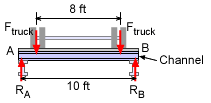
Like all mechanics problems, a free body diagram of the structure is critical in solving the problem. In this case, a 19 ton truck is on a 10 ft wide bridge. The rear wheels are 8 ft apart and carry 80% of the load. The total truck load (including truck) is 19 tons. Thus, each of the rear wheel sets (one on each side) will carry 40% of the 19 tons, giving, Ftruck = 0.4 (19 tons) (2 kip/ton) = 15.2 kip The reaction forces are the same as the truck force due to symmetry. RA = RB = 15.2 kip |
|
| Shear and Moment Diagrams |
||
|
|
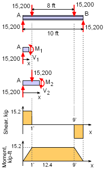
A shear and moment diagram of the channel will help identify the maximum shear load and bending moment. Both of these values are needed to determine the maximum shear and bending stress. Due to symmetry, only two cuts are needed to construct the shear and moment diagrams. The first cut is between RA and the first wheel. V1 = 15.2 kip The second cut is between the left wheel load and the center line of the channel beam. V2 = 0.0 kip The moment in the channel beam is constant between the wheels and the shear is zero. The maximum shear is at either end of the channel. The moment maximum is between the wheels. |
|
| Shear Stress |
||
|
|
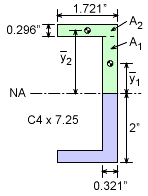
As with any structural member, the shear stress varies across the channel cross section. It starts at zero at the top and bottom surface and is a maximum at the center or neutral axis. The shear stress at any point on the section is given by To calculate the shear stress four values are required, V, I, b and Q. The maximum shear load, V, has been found to be 15.2 kip at either end of the channel. The moment of inertia about the NA can be found in the appendix for a C4 x 7.35 channel and is given as 4.59 in4. The member width, b, at the neutral axis is 0.321 in. The final term, Q must be calculated using the method of parts. The section above the cut line (NA) is split into two rectangular parts as shown in the diagram. This gives, = (1.704/2)(1.704)(0.321) = 0.4660 + 0.9434 = 1.4095 in3 Substituting all values in the shear stress equation gives, This is less than the allowable shear stress of 18 ksi. |
|
| Bending Stress |
||
|
The bending stress also needs to be checked. Unlike shear stress, the maximum bending stress occurs at the point furthest from the neutral axis. This is at the top or bottom surface. Using the bending stress equation gives, σ = -My/I = -(15.2 kip-ft)(12 in/ft)(-2 in) / (4.59 in4) = 79.48 ksi This is higher than the allowing bending stress of 36 ksi. Thus, the bending stress will cause failure even though the shear stress is below the allowable level. |
||
Practice Homework and Test problems now available in the 'Eng Mechanics' mobile app
Includes over 500 free problems with complete detailed solutions.
Available at the Google Play Store and Apple App Store.


