| Ch 10. Virtual Work & Potential Energy | Multimedia Engineering Statics | ||||||
|
Virtual Work |
Potential Energy | ||||||
| Virtual Work | Case Intro | Theory | Case Solution | Example |
| Chapter |
| 1. Basics |
| 2. Vectors |
| 3. Forces |
| 4. Moments |
| 5. Rigid Bodies |
| 6. Structures |
| 7. Centroids/Inertia |
| 8. Internal Loads |
| 9. Friction |
| 10. Work & Energy |
| Appendix |
| Basic Math |
| Units |
| Sections |
| eBooks |
| Dynamics |
| Fluids |
| Math |
| Mechanics |
| Statics |
| Thermodynamics |
| ©Kurt Gramoll |
|
|
||
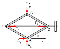 Free-body Diagram Before Displacement
|
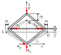
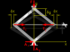
To solve for the tension in the shaft, the principle of virtual work can be used. Begin with a free-body diagram of the jack as shown at the left. Hold point A fixed and let point B undergo a virtual displacement δy in the positive y direction. The deflection is assumed to be small even though it is large in the diagram. Because point A is fixed, the reaction forces at A does no work. |
|
| Rod Tension and Virtual Displacement |
||
|
|
The tension in the shaft can be broken down into two equal and opposite components, T1 and T2. Because these components remain horizontal, they do no work in the vertical direction. The total virtual work performed during the virtual displacement is the sum of the virtual work performed by the two components of the tension, and the virtual work performed by the weight of the automobile, δU = δUT1
+ δUT2 + δUF
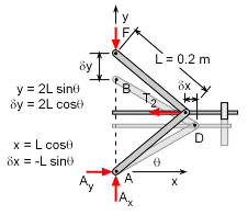
The total virtual work performed during the virtual displacement is the sum of the virtual work performed by the two components of the tension, and the virtual work performed by the weight of the automobile, δU = 2T δx - F δy Notice that the equation for the virtual work is expressed in terms of the virtual displacements. To solve, express the virtual displacements in terms of a common variable. The vertical displacement of point B can be expressed in terms of the angle θ, y = 2L sinθ
|
|
|
The horizontal displacement of points C and D can also be expressed in terms of the angle θ: x = 2L cosθ
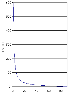
Substitute the expressions for δx and δy into δU: δU = 2T(-L sinθ) - F 2L cosθ = 0 T = -F/tanθ The tension, T, vs. the angle, θ, is graphed in the diagram at the left. Observe that the tension increases as θ approaches 0. Thus, under normal operating conditions (30o≤ θ ≤ 60o), the angles at which the tension is the greatest and the least are θT max = 30o θT min = 60o |
|
