| Ch 9. 3-D Motion of a Rigid Body | Multimedia Engineering Dynamics | ||||||
| Translating Coordinates | Rotating Coordinates | Inertia & Ang. Momentum |
Equations of Motion |
||||
| Equations of Motion | Case Intro | Theory | Case Solution |
| Chapter |
| - Particle - |
| 1. General Motion |
| 2. Force & Accel. |
| 3. Energy |
| 4. Momentum |
| - Rigid Body - |
| 5. General Motion |
| 6. Force & Accel. |
| 7. Energy |
| 8. Momentum |
| 9. 3-D Motion |
| 10. Vibrations |
| Appendix |
| Basic Math |
| Units |
| Basic Dynamics Eqs |
| Sections |
| eBooks |
| Dynamics |
| Fluids |
| Math |
| Mechanics |
| Statics |
| Thermodynamics |
| ©Kurt Gramoll |
|
|
||
|
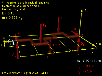
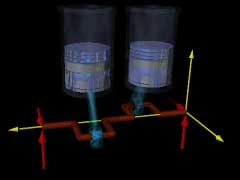
Begin with a diagram at the instant the crankshaft is in the horizontal plane. Since the principal axes of inertia are not readily known for either the center of gravity or point O, let the reference frame xyz be located at point O as shown, |
||
|
|
||
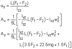
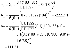
The crankshaft only rotates about the z-axis, ωx = ωy = 0, ωz = ω = 104 rad/s The angular equations (Eqs. 1 in the theory section) simplify to ΣMx = Iyz ωz2 - Ixz αz2 The moments are due to forces F1, F2, Ay and Ax, -Ay (5L) + F2 (3.5L) + 9mg (2.5L) + F1 (1.5L) These equations can be rearranged in terms of the three unknowns Ax, Ay, and αz, giving |
||
|
|
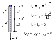
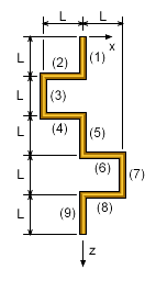
To solve these three equations, the inertia terms, Izz, Iyz, and Ixz, need to be determined. To find the inertia terms, split the shaft into 9 straight slender rods. The total moment of inertia and product of inertia terms can be found by summing the inertia of all sections about themselves, and using the parallel axis theorem. This gives, Izz = Izz-1 + Izz-2 + Izz-3 + Izz-4 + Iyz = 0 (all sections in x-z plane at given instant) Ixz = 0 + (-L/2)(L)m + (-L)(1.5L)m + (-L/2)(2L)m + Substituting the inertia terms and known forces, F1 = 100 N, and F2 = 65 N, gives |
|
Practice Homework and Test problems now available in the 'Eng Dynamics' mobile app
Includes over 400 free problems with complete detailed solutions.
Available at the Google Play Store and Apple App Store.
