| Ch 9. Columns | Multimedia Engineering Mechanics | ||||||
|
Basic Columns |
Fixed Columns |
Eccentric Loads |
|||||
| Basic Columns | Case Intro | Theory | Case Solution | Example |
| Chapter |
| 1. Stress/Strain |
| 2. Torsion |
| 3. Beam Shr/Moment |
| 4. Beam Stresses |
| 5. Beam Deflections |
| 6. Beam-Advanced |
| 7. Stress Analysis |
| 8. Strain Analysis |
| 9. Columns |
| Appendix |
| Basic Math |
| Units |
| Basic Mechanics Eqs |
| Sections |
| Material Properties |
| Structural Shapes |
| Beam Equations |
| eBooks |
| Dynamics |
| Fluids |
| Math |
| Mechanics |
| Statics |
| Thermodynamics |
| ©Kurt Gramoll |
|
|
|||||
| Column Buckling |
|||||
|
|
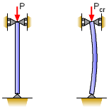
In addition to understanding stress and material failure due to tension and compression, buckling needs to be investigated. While buckling can occur in plates and shells, column buckling is most common and easiest understood. If an object buckles, it does not necessarily mean it has failed, but a buckled structure will experience significant lateral deflection. Furthermore, a buckled column structure will not sustain any significant additional load. Column buckling is not an exact science, and many issues can cause pre-mature buckling, such as misaligned loads, material imperfections, and varying structural dimensions. However, for even perfect systems, buckling will be significantly lower than the crushing or compression limit of the material. |
||||
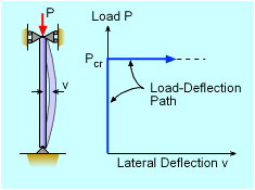 Load-Deflection Diagram for Column Buckling |
When any long slender object is loaded in the axial direction, it will buckle when the load reaches a particular load. This load, called the critical load, Pcr, is when the object will deflect significantly in the lateral direction (perpendicular to the load). After buckling starts, the structure will not be able to sustain any additional loads. For an ideal column, buckling will not occur until Pcr has been reached. Thus the column will have no lateral deflection up to Pcr, and then all at one time, the member will deflect. This is plotted in the diagram at the left. The beam's internal resistance to bending keeps the beam from buckling. However, at some point, the potential moment generated by the axial load will be greater than the internal resisting moment, and the column will buckle. For columns, it is generally assumed that if buckling occurs, the structure has failed. Thus, a column structure should be designed not to buckle. |
||||
| Euler's Formula for Simply Supported Column (pinned-pinned) |
|||||
|
|
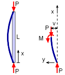
The theoretical buckling load, Pcr, for a basic column can be determined and the resulting equation(s) are called Euler's formula. The simplest column to develop the buckling equations is when both ends are simply supported by a pin joint (also called a pinned-pinned column). This means that it can not deflect at the joint, but it can rotate as shown in the diagram at the left. If the column is loaded and starts to deflect laterally, then the moment in the column must equal the moment cased by the load P at each end. This condition can be better understood by taking a section cut at any point along the column and constructing a free-body diagram. Summing the moments at any point along the lower column section gives, ΣM = 0 M + Pv = 0 The moment M, is drawn in the positive direction, even though it may be actually act in the opposite direction. The distance v is the lateral deflection at the cut location, x, from the bottom pin joint. |
||||
|
If the column is rotated 90o, it becomes a simply supported beam. As such, the beam bending equations are still valid and can be used. Recall from beam deflections, the moment is related to the deflection as Combining the two previous equations gives This is a standard differential equation which has a general solution of where C1 and C2 are unknown constants that depend on the boundary conditions of the differential equation. In this particular case, both ends of the beam or column are pinned so that v = 0 when x = 0 and x = L. The first condition, vx=0 = 0 gives |
||||
|
|
0 = C1 (0) + C2 (1) => C2 = 0 The second condition, vx=L = 0 gives Since C1 cannot be zero (would be trivial solution, v = 0), the sin function must be equal to zero which requires, |
||||
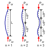 First Three Column Buckling Modes |
The lowest load is when n equals 1, and is referred to as the critical load Pcr. Euler's formula for a pinned-pinned column is
Other buckling modes (i.e. n > 1) do exist, but are less common since it takes a larger load to produce this configuration. The first three buckling modes are shown in the diagram at the left. |
||||
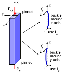 Simply Supported Column Possible Buckling Directions |
Buckling Direction |
||||
|
Simply supported columns (pinned at each end) will buckle around the axis with the lowest moment of inertia. For example, for a rectangular cross sectional column, as shown at the left, the column will buckle around the z-axis since Iz will be less than Iy. If it is an unsymmetric cross section, then it may not be obvious and may even buckle at a particular angle between the y- and z-axis. In this eBook, only symmetric cross section members are considered. When calculating buckling, check both directions to find the lowest moment of inertia. Then use that for the critical buckling load calculations. |
|||||
