| Ch 9. Brayton Cycle | Multimedia Engineering Thermodynamics | ||||||
|
Brayton Cycle |
Intercooling and Reheating |
||||||
| Brayton Cycle | Case Intro | Theory | Case Solution |
| Chapter |
| 1. Basics |
| 2. Pure Substances |
| 3. First Law |
| 4. Energy Analysis |
| 5. Second Law |
| 6. Entropy |
| 7. Exergy Analysis |
| 8. Gas Power Cyc |
| 9. Brayton Cycle |
| 10. Rankine Cycle |
| Appendix |
| Basic Math |
| Units |
| Thermo Tables |
| eBooks |
| Dynamics |
| Fluids |
| Math |
| Mechanics |
| Statics |
| Thermodynamics |
| ©Kurt Gramoll |
|
|
||
|
A turbojet aircraft is held stationary by the brakes to load seriously injured people. The force applied to the brakes needs to be determined. Assumptions:
|
||
|
|
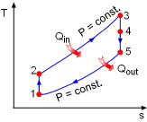
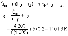
Model the cycle in the aircraft engine as an ideal jet-propulsion cycle. The T-s diagram of the ideal jet-propulsion cycle described is shown on the left. The braking force equals the thrust developed by the engine when the airplane is stationary. The thrust can be determined by where The airplane is stationary on the ground and the air velocity at the inlet of the engine is negligible. Also, the effect of diffuser is negligible. Thus, the thrust can be simplified as The exit velocity of the nozzle can determined by the energy balance of the nozzle. In steady-flow condition, it is The above analysis shows that in order to calculate the exit velocity, temperatures at state 4 and state 5 need to be determined first. State 1: State 2: Process 1-2: isentropic compression. State 3: P3 = P2 = 1,000 kPa Heat transfer into the cycle equals, The temperature at state 3 is |
|
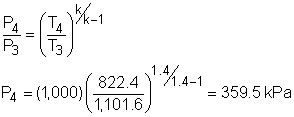
State 4: h3 - h4 = h2 - h1 Process 3-4: isentropic expansion in turbine State 5: P5 = P1 = 100 kPa Process 4-5 is an isentropic expansion process in nozzle. After determining state 4 and state 5, the exit velocity at the nozzle can be determined as Substitute v5 and mass flow rate of air into the expression of thrust yields, F = 8(711.5) = 5,692 N To hold the airplane stationary, 5,692 N force needs to be applied to the brakes to balance the thrust developed by the engine. |
||


