| Ch 9. Columns | Multimedia Engineering Mechanics | ||||||
|
Basic Columns |
Fixed Columns |
Eccentric Loads |
|||||
| Basic Columns | Case Intro | Theory | Case Solution | Example |
| Chapter |
| 1. Stress/Strain |
| 2. Torsion |
| 3. Beam Shr/Moment |
| 4. Beam Stresses |
| 5. Beam Deflections |
| 6. Beam-Advanced |
| 7. Stress Analysis |
| 8. Strain Analysis |
| 9. Columns |
| Appendix |
| Basic Math |
| Units |
| Basic Mechanics Eqs |
| Sections |
| Material Properties |
| Structural Shapes |
| Beam Equations |
| eBooks |
| Dynamics |
| Fluids |
| Math |
| Mechanics |
| Statics |
| Thermodynamics |
| ©Kurt Gramoll |
|
|
||
|
|
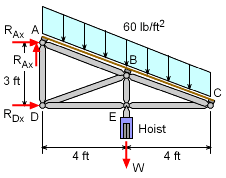
The canopy currently exists and a new hoist needs to be installed under the canopy to move packages and equipment around on the dock. The logical location for the hoist is to attach it to the center truss node as shown in the diagram. The actual load W is not known and needs to be determined. The roof load is given, 60 lb/ft2, and the truss configuration is known. The question is what is the maximum load W before one of the members buckle? The canopy requires a factor of safety of 2 which needs to be included in the calculations. There is a canopy truss every 5 feet along the length of the dock, so each truss needs to support at least 5 feet of the roof load. The first step will be to solve for the loads in the truss members using both the joint method and the section method from statics. |
|
| Tension and Compression Members |
||
|
|
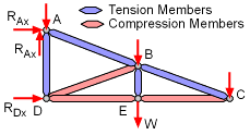
Before calculating the force in every member, some members can be eliminated from consideration. Recall, the problem is only concerned about buckling so just the compression members are of interest. The top two members, AB and BC, will be in tension as the canopy is pushed downward by the roof and the hoist loads. Next, the full hoist load will be carried in tension by member BE since they are collinear at joint E. Likewise, from inspection members DB, DE, and EC will be in compression resisting the roof and hoist loads. If DB is in compression then AD will be in tension. This leaves only members DB, DE, and EC. |
|
| Roof Load Distribution |
||
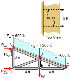 Roof Load Distribution on Truss |
Since the trusses are spaced every 5 feet along the length of the dock, each truss will need to carry the roof load over 5 feet. The total load will be Truss Total Load = (60 lb/ft2)(8 ft)(5 ft) = 2,400 lb The roof is connected to the truss through the joint points and so the roof load is distributed to each of the joints as concentrated forces. However, the distribution is not equal. The outside two joints (A and C) will only carry half of what the center joint will carry. FA = FC = (60 lb/ft2)(2 ft)(5 ft) = 600 lb FB = (60 lb/ft2)(4 ft)(5 ft) = 1,200 lb The angle θ can be determined from the geometry, tanθ = 3/8 => θ = 20.56o |
|
| Member Loads in EC and DE |
||
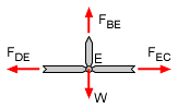 Joint E Free Body Diagram |
Notice that all members at joint E are perpendicular. This requires the force in member DE equal the force in member EC. Thus, FDE = FEC There are many ways to find the load in truss members, but one useful method is the method of joints. This method requires one to analyze a single joint with only two unknown member forces. This can be done at joint C. |
|
 Joint C Free Body Diagram |
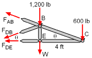
The equilibrium equations can be applied to joint C, giving ΣFy = 0 ΣFx = 0 The negative value means it is under compression, as originally assumed. Notice, that both members are not effected by the hoist load. In other words, none of the hoist load will be supported by members BC or EC. Therefore, members BC or EC are not critical when the hoist is used. |
|
| Member Load in DB |
||
|
|
The other compression member is DB. The load in DB can best be determined using the method of sections. Making a section cut through members DE, DB, and AB allows solving for all three members. Taking moments about joint C will give one equation and one unknown, ΣMC = 0 W (4) +1,200 (4) + FDBcosθ (1.5) + FDBsinθ (4) = 0 FDB = -1.424W - 1,709 lb The compression force in FDB is a function of the hoist weight W. |
|
| Buckling load of Member DB |
||
|
The buckling load of member DB can be determined using Euler's Formula for simply supported (pinned-pinned ends) columns. The moment of inertia for the 1.5 inch pipe with a wall thickness of 1/16 in is The length of member DB is L = (42 + 1.52)1/2 = 4.272 ft = 51.26 in The objective is to find the largest hoist load, W, that can be applied without buckling with a a factor of safety of 2.0. This gives, W = 1,593 lb Thus, the hoist and its load can be a maximum of 1,593 lb. This should be sufficient to assist in moving most packages and equipment around on the dock. |
||
