| Ch 8. Strain Analysis | Multimedia Engineering Mechanics | ||||||
|
Plane Strain |
Mohr's Circle for Strain |
Strain Gages |
|||||
| Strain Gages and Strain Rosette | Case Intro | Theory | Case Solution | Example |
| Chapter |
| 1. Stress/Strain |
| 2. Torsion |
| 3. Beam Shr/Moment |
| 4. Beam Stresses |
| 5. Beam Deflections |
| 6. Beam-Advanced |
| 7. Stress Analysis |
| 8. Strain Analysis |
| 9. Columns |
| Appendix |
| Basic Math |
| Units |
| Basic Mechanics Eqs |
| Sections |
| Material Properties |
| Structural Shapes |
| Beam Equations |
| eBooks |
| Dynamics |
| Fluids |
| Math |
| Mechanics |
| Statics |
| Thermodynamics |
| ©Kurt Gramoll |
|
|
||
|
Example |
|
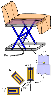
A hydraulic piston is used to move a dental chair up and down. To help assist in designing the piston, three strain gages have been attached directly to the piston as shown in the diagram on the left. When the chair is raised, the strain gages give strains as εa = 80×10-6 m/m (1) Determine the principal strains and the principal strain directions for the given set of strains. (2) Compute the strain in a direction -60° (clockwise) with the x axis. |
||
| Solution |
||
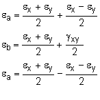
The first step is to transform the strains to the standard x-y coordinate directions. This can be done by rotating the three unknown strains, εx, εy and γxy, into the three known stains εa, εb and εc. Using the equations for a 45° strain rosette, these strains are, εx = εa εy = εc γxy = 2εb - (εa + εc) Substituting the actual strains into the equations gives, εx = 80×10-6 m/m |
||
|
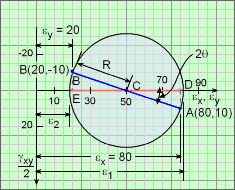
To determine the principal strains, the strains are plotted on a Mohr's circle as shown in the diagram on the left. The coordinates of point A are εx = 80 and γxy/2 = 10 and the coordinates of B are εy = 20 and -γxy/2 = -10. The x axis is represented by the radius CA, and the y axis by the radius CB. Radius of the circle is R = ((80 - 50)2 + (10)2)1/2 = 31.62 The principal strains are, ε1 = (50 + 31.62)×10-6 ε2 = (50 - 31.62)×10-6 The angle between the maximum strain axis and the x axis is, θ = (1/2) (∠ACD) = (1/2) tan-1(10/30) = 9.217 ° |
|
 Mohr's Circle for 60° Rotation |
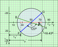
To compute the strains in a new direction, Mohr's circle can again be used. For strains in a direction 60° clockwise with the x axis, rotate the x axis two times 60° (i.e., 120°) as shown with line FG. The strain at that direction are, εx* = {50 - 31.62 cos(180 - 120 - 18.43)}×10-6 To compute the strain in a direction 90° with this line, it can be rotated two times 90° or 180°, which is diametrically opposite to it. εy* = {50 + 31.62 cos(180 - 120 - 18.43)}×10-6 Corresponding shear strain is, γxy* = 2 {31.62 sin(180 - 120 - 18.43)}×10-6 The new strains are represented as point F and G on the diagram at the left. |
|


