| Ch 8. Strain Analysis | Multimedia Engineering Mechanics | ||||||
|
Plane Strain |
Mohr's Circle for Strain |
Strain Gages |
|||||
| Strain Gages and Strain Rosette | Case Intro | Theory | Case Solution | Example |
| Chapter |
| 1. Stress/Strain |
| 2. Torsion |
| 3. Beam Shr/Moment |
| 4. Beam Stresses |
| 5. Beam Deflections |
| 6. Beam-Advanced |
| 7. Stress Analysis |
| 8. Strain Analysis |
| 9. Columns |
| Appendix |
| Basic Math |
| Units |
| Basic Mechanics Eqs |
| Sections |
| Material Properties |
| Structural Shapes |
| Beam Equations |
| eBooks |
| Dynamics |
| Fluids |
| Math |
| Mechanics |
| Statics |
| Thermodynamics |
| ©Kurt Gramoll |
|
|
||
|
|
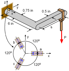
In order to determine the location and weight of a particular hanging load P, a strain rosette is attached to the top of the bracket near the wall (assume strain gages are at the wall). The rosette has three gages, each are 120o apart as shown in the diagram. The bracket material is steel, E = 29,000 ksi and ν = 0.29. When the weight P is placed at a distance s on the rectangular bracket arm, the three gages measure the following strains, εa = 224.8 μ From these three strains, the load P and the distance s need to be determined. |
|
| Transform Gage Strains to Strain Element |
||
|
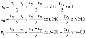
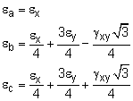
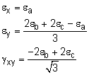
The first step is to transform the strain gage strains to strains that can be represented in a normal x-y strain element. This can be done by rotating the three unknown strains, εx, εy and γxy. into the three known stains, εa, εb and εc. using the basic strain rotation equation, εx' = (εx + εy)/2 + (εx + εy)/2 cos2θ + γxy/2 sin2θ Applying this equation three times, once for each gage where θa = 0o, or θb = 120o, or θc = 240o, gives, These simplify to Substituting the first equation into the second two and solving for εx and εy gives |
||
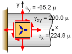 Gage Direction Strains Transformed to x-y Strain Element |
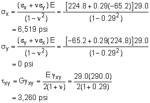
Substituting the actual gage values gives the final strains in the x-y coordinate system, εx = 224.8 μ εy = [2(-118.3 μ) + 2(132.9 μ) - 224.8 μ]/3 γxy = [-2(-118.3 μ) + 2(132.9 μ)]/1.7321 Notice, the y-direction normal strain is not zero due to Poisson's effect even though the stress will be zero. |
|
| Stresses at Gage Rosette |
||
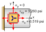 Actual x-y Stresses at Gage Location |
Hooke's law can be used to calculate the x-direction stress and the shear stress. |
|
| Bending and Twisting Moment |
||
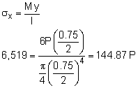
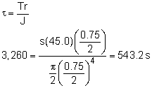
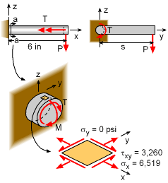 Bending Moment (M) and Twisting Moment (T) and |
The load P will cause both a bending moment and a twisting moment at the wall where the strain gages are located. The bending moment is Mbending = P (6 in) This moment will cause a bending stress at the top of the circular bar at the gage location. P = 45.0 lb |
|
The twisting moment is Ttwisting = Ps This torque will cause a shear stress in the circular bar. s = 6.0 in |
||
Practice Homework and Test problems now available in the 'Eng Mechanics' mobile app
Includes over 500 free problems with complete detailed solutions.
Available at the Google Play Store and Apple App Store.
