| Ch 6. Entropy | Multimedia Engineering Thermodynamics | ||||||
| Entropy | Tds Relations |
Entropy Change |
Isentropic Process |
Isentropic Efficiency |
Entropy Balance (1) |
Entropy Balance (2) |
Reversible Work |
| Reversible Steady-flow Work | Case Intro | Theory | Case Solution |
| Chapter |
| 1. Basics |
| 2. Pure Substances |
| 3. First Law |
| 4. Energy Analysis |
| 5. Second Law |
| 6. Entropy |
| 7. Exergy Analysis |
| 8. Gas Power Cyc |
| 9. Brayton Cycle |
| 10. Rankine Cycle |
| Appendix |
| Basic Math |
| Units |
| Thermo Tables |
| eBooks |
| Dynamics |
| Fluids |
| Math |
| Mechanics |
| Statics |
| Thermodynamics |
| ©Kurt Gramoll |
|
|
||
|
A small power plant using hydraulic turbines is planned. The number of intake pipes which intake water from a reservoir to the turbines needs to be determined. Assumptions:
|
||
|
|
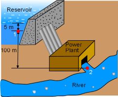
The schematic of the power plant is shown on the left. Take the pipes and the turbines together as a control volume. Denote the inlet of the intake pipes as 1 and the outflow of the turbine as 2.The reversible steady-flow work generated by this power plant is where The first term on the left-hand side is the pressure term. Point 1 is located 5 meter under the water surface in reservoir. So pressure P1 is P1 = ρgh + Patm= 1000(9.8)(5) + 100,000 Point 2 is located at the outflow of the power plant. Its pressure equals the ambient pressure, P2 = 1.0 bar The second term on the left-hand side is the kinetic energy term. Water enters the pipes with a velocity of 1 m/s and leaves the turbine as the same velocity. Hence, there is no kinetic energy change when water flows from point 1 to point 2. That is, ΔKE = 0 The third term on the left-hand side is the potential energy term. Water flowing from point 1 (100 m higher than point 2) to point 2 experiences a potential energy change of Substituting the three terms into the expression for reversible steady-flow work gives |
|
This power plant needs to generate 1 MW power, hence, Substituting this to the expression of the reversible steady-flow work gives 1,000,000 = 1,029,000 Water enters the intake pipe with a velocity of 1 m/s. The flow rate through each 0.5 m diameter pipe is In order to intake 0.97 m3 of water through the pipes per second, the number of the pipes needed is N = |
||


