| Ch 6. Structures | Multimedia Engineering Statics | ||||||
| 2-D Trusses: Joints | 2-D Trusses: Sections | 3-D Trusses | Frames and Machines | ||||
| Frames and Machines | Case Intro | Theory | Case Solution |
| Chapter |
| 1. Basics |
| 2. Vectors |
| 3. Forces |
| 4. Moments |
| 5. Rigid Bodies |
| 6. Structures |
| 7. Centroids/Inertia |
| 8. Internal Loads |
| 9. Friction |
| 10. Work & Energy |
| Appendix |
| Basic Math |
| Units |
| Sections |
| eBooks |
| Dynamics |
| Fluids |
| Math |
| Mechanics |
| Statics |
| Thermodynamics |
| ©Kurt Gramoll |
|
|
||
|
|
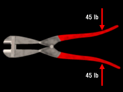
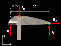
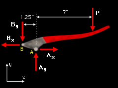
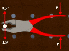
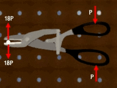
This problem requires a number of steps to solve for the force at Q. First, separate the components of the bolt-cutters and label the forces acting on each part. Since the bolt-cutters are symmetric, only the components of the top half will be considered. From the free-body diagram of the cutter section, one can observe that there is only one force in the x direction. This means that ΣFx = 0 = Bx If force Bx is equal to zero, the diagram for the handle section shows that ΣFx = Ax - Bx = 0 Solving for Bx gives Bx = Ax = 0 Now, the y component of force B needs to be determined. To do this, take the moment about point A for the handle, ΣMA = By (1.25") - 45 lb (7") = 0 Solving for By gives By = 252 lb Now, find the force at Q by summing the moments about point C for the cutter section, ΣMC = By (2.5") - Qtop (0.75") = 0 Solving for Q then yields the amount of force required by the top components to cut the lock, Qtop = 840 lb There will be an equal and opposite force on the bottom cuter edge, Qbottom = 840 lb If the same force is applied to machines such as pliers or metal snips, the resultant force will vary due to the different configurations. The approximate magnitude for the metal snips is comparable to the bolt-cutters, but the pliers' magnitude is much smaller. Thus each tool's design plays a major role in its function. In this problem, only the total force exerted at point Q was needed. In reality, it is the stress applied to the lock that will cause it to break. Using bolt-cutters and metal snips, the force is applied over a small area due to the cutting edges. However, with pliers, the force is applied over a larger area and therefore produces less stress. In this respect, many different factors are important in tool design. |
|
