| Ch 6. Structures | Multimedia Engineering Statics | ||||||
| 2-D Trusses: Joints | 2-D Trusses: Sections | 3-D Trusses | Frames and Machines | ||||
| 3-D Trusses/Space Trusses | Case Intro | Theory | Case Solution | Example |
| Chapter |
| 1. Basics |
| 2. Vectors |
| 3. Forces |
| 4. Moments |
| 5. Rigid Bodies |
| 6. Structures |
| 7. Centroids/Inertia |
| 8. Internal Loads |
| 9. Friction |
| 10. Work & Energy |
| Appendix |
| Basic Math |
| Units |
| Sections |
| eBooks |
| Dynamics |
| Fluids |
| Math |
| Mechanics |
| Statics |
| Thermodynamics |
| ©Kurt Gramoll |
|
|
||
|
|
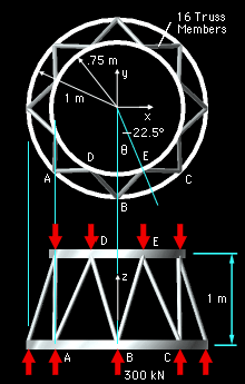
Since all members are symmetrical around the inter-stage structure, all members will have the same load. Using the method of joints, the forces at joint B on the bottom ring is analyzed by summing the forces, ΣFB = 0 The free-body diagram includes the external thrust load and all member forces acting at joint B. Since Joint B is in static equilibrium, the summation of all force vectors must equal zero. Since this is a 3D problem, all forces will be represented in the vector i, j, k format. The total thrust load of 2,400 kN is evenly distributed around the inter-stage structure so each joint will have to withstand a vertical load of 300 kN. FT = 300 k
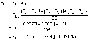
Use the location of points B and E to define the unit directional vector of FBE. Ex = 0.75 sin22.5 = 0.2870 m Bx = 0 m BE = ((0.2870 - 0)2 + (-0.6929
- (-1))2 The vector FBE in i, j, k format is The member force FBD is similar to FBE except the x component is reversed. The magnitudes will be the same: FBD = FBE (-0.2645i + 0.2830j + 0.9217k) If forces are summed in the z direction, ΣFz = 0, only one unknown remains, FBE. Solving for FBE gives 2 FBE 0.9217 + 300 = 0 FBE = -162.7 kN compression |
|


