| Ch 6. Advanced Beams | Multimedia Engineering Mechanics | ||||||
|
Composite Beams |
Unsymmetric Bending |
||||||
| Composite Beams | Case Intro | Theory | Case Solution | Example |
| Chapter |
| 1. Stress/Strain |
| 2. Torsion |
| 3. Beam Shr/Moment |
| 4. Beam Stresses |
| 5. Beam Deflections |
| 6. Beam-Advanced |
| 7. Stress Analysis |
| 8. Strain Analysis |
| 9. Columns |
| Appendix |
| Basic Math |
| Units |
| Basic Mechanics Eqs |
| Sections |
| Material Properties |
| Structural Shapes |
| Beam Equations |
| eBooks |
| Dynamics |
| Fluids |
| Math |
| Mechanics |
| Statics |
| Thermodynamics |
| ©Kurt Gramoll |
|
|
||||||||
| Introduction |
||||||||
|
|
Composite beams are constructed from more than one material to increase stiffness or strength (or to reduce cost). Common composite-type beams include I-beams where the web is plywood and the flanges are solid wood members (sometimes referred to as "engineered I-beams"). Pipe beams sometimes have an outer liner made from another type of material. In this section, two-material composite beams will be examined. Of course, two materials can be arranged in multi-sections but only two different type of materials will be used. Beams with three or more materials are possible, but are rare and increase the complexity of the equations. |
|||||||
| Two-material Composite Beams - Axial Load |
||||||||
|
|
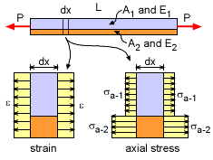
The simplest loading in a composite beam is axial loading. The strain is continuous across the beam cross section but the stress is discontinuous as shown in the diagram at the left. When axially loaded, the normal strains are equal since the two materials are rigidly attached. From Hooke's law, this gives ε1 = ε = σ1/E1 Eliminating ε gives, σ1/E1 = σ2/E2 The total load P must equal the stresses times their respective areas, or P = A1σ1 + A2σ2 Combining the previous two equations gives
|
|||||||
| Two-material Composite Beams - Moment Load |
||||||||
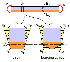 Strain and Stress in Two-material Composite Beam undergoing Moment Loading |
Similar to axially loaded two-material beams, when a beam is subjected to a moment, the strain is still continuous, but the stress is discontinuous. Where the stress and strain in axial loading is constant, the bending strain and stress is a linear function through the thickness for each material section as shown at the left. The bending stress equations require the location of the neutral axis. For non-composite beams, the neutral axis (NA) is the centroid of the cross section. This is not the case for composite beams and is one of the main difficulties in solving for the bending stress. Thus, the first step in calculating bending stress is locating the NA. Then the bending stress equation, My/I, can be used to find the stress in each material. There will be a separate equation for the bending stress in each material section. |
|||||||
| Neutral Axis (NA) Location |
||||||||
|
As with non-composite beams, the neutral axis (NA) is the location where the bending stress is zero. The location of the NA depends on the relative stiffness and size of each of the material sections. Generally, the NA location is determined relative to the bottom surface of the beam. However, this is not mandatory, and the location can be relative to any location. If the bottom is used, then the NA axis is a distance "h" from the bottom as shown in the diagram at the left. |
||||||||
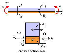 Neutral Axis Location for Composite Beam |
The distance h can be determined by recalling that the stresses through the cross section must be in equilibrium. Summing forces in the x-direction gives, Recall, the bending stress in any beam is related to the radius of curvature, ρ, as σ = -Ey/ρ, Since the curvature is the same at all locations of a given cross section, this equation simplifies to The two integrals are the first moment of each material area which is commonly noted as simply Q, giving
Generally, Q is not solved using the integral form since the centroid of each material area will be known (or found in the Sections appendix). Thus the equation can also be written as
where y1 and y2 are the distance from the NA to the centroid of the material area. Notice, "h" is not in this equation, but both y1 and y2 depend on h. Thus, the only unknown will be h and can be determined. Note, y will be negative if the centroid of the material area is below the NA. |
|||||||
| Bending Stresses |
||||||||
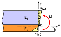 Neutral Axis Location for Composite Beam |
The bending stress in a composite beam can be found by using the moment equilibrium
equation at any internal location. Summing the moments give,
Using the relationship between the bending stress and the radius of curvature, σ = -Ey/ρ, gives, Notice that the integral is the second moment of the area which is also the area moment of inertia, I. This simplifies to Rearranging gives The bending stress in each material section is related to the beam curvature as Substituting the curvature into the above equations gives the final bending stress for each material section.
Each equation is only valid for its material area. Also, these two equations are for two-material composite beams only. |
|||||||
| Alternative Method - Equivalent Area |
||||||||
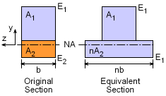 Equivalent Area Method Cross Section |
Another way to analyze composite beams is to use an equivalent area to represent the increased (or decreased) stiffness of the second material. The new equivalent cross section is assumed to be made completely from material 1. The area of material 2 is simply scaled to account for the stiffness difference using the scaling factor, n, n = E2 / E1 Note, the area scaling must only be done in the horizontal direction. The vertical dimension of either material cannot be changed. The neutral axis can be found by finding the centroid of the full cross section, as was done with single material beams. Also, the bending stresses can be determined from the basic beam bending equation, where I is the moment of inertia of the full equivalent cross section, and y is the distance from the neutral axis (down is negative). While this method simplifies the equations, it is still basically the same calculations. It is important to be make sure the scaling factor, n, is correctly determined and applied to the area of the second material. |
|||||||
Practice Homework and Test problems now available in the 'Eng Mechanics' mobile app
Includes over 500 free problems with complete detailed solutions.
Available at the Google Play Store and Apple App Store.

