| Ch 5. Rigid Body Equilibrium | Multimedia Engineering Statics | ||||||
|
2-D and 3-D Supports |
Equilibrium in 2-D |
Equilibrium in 3-D |
Indeterminate Objects | 2 and 3 Force Members | |||
| Equilibrium in 2-D | Case Intro | Theory | Case Solution | Example |
| Chapter |
| 1. Basics |
| 2. Vectors |
| 3. Forces |
| 4. Moments |
| 5. Rigid Bodies |
| 6. Structures |
| 7. Centroids/Inertia |
| 8. Internal Loads |
| 9. Friction |
| 10. Work & Energy |
| Appendix |
| Basic Math |
| Units |
| Sections |
| eBooks |
| Dynamics |
| Fluids |
| Math |
| Mechanics |
| Statics |
| Thermodynamics |
| ©Kurt Gramoll |
|
|
||
|
|
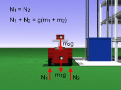
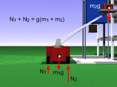
Use the support conventions presented in previous section to make a free-body diagram of the truck and bricks. Assume that the normal forces acting on the wheels, the center of mass of the truck, and the center of mass of the bricks all lie in the x-y plane. Summing the forces in both the x and y direction, and the moments about point the center of gravity of the truck, point A, gives, ΣFx
= 0 (1) The first equation shows that there is no force exerted on the wheels by the ground in the horizontal direction. Using the third equation, solve for N2, N2 = N1 + L2/L1 m2g cosθ and then substitute into the second equation, N1 + N1 + L2/L1 m2g cosθ = g(m1 + m2) N1 = g/2 (m1 + m2) - L2/L1 m2g/2 cosθ Solving N1 = 9.81/2 (2,000 + 400) N1 = 2,063 N Substituting back into the second equation gives N2 as, N2 = g(m1 + m2) + N1 N2 = 9.81 (2,000 + 400) - 2,063 N2 = 21,480 N Notice that indeed N1 + N2 = 23,540 N = g(m1 + m2) |
|


