| Ch 4. Beam Stresses | Multimedia Engineering Mechanics | ||||||
|
Bending Strain and Stress |
Beam Design |
Shear Stress |
Built-up Beams |
||||
| Built-up Beams | Case Intro | Theory | Case Solution | Example |
| Chapter |
| 1. Stress/Strain |
| 2. Torsion |
| 3. Beam Shr/Moment |
| 4. Beam Stresses |
| 5. Beam Deflections |
| 6. Beam-Advanced |
| 7. Stress Analysis |
| 8. Strain Analysis |
| 9. Columns |
| Appendix |
| Basic Math |
| Units |
| Basic Mechanics Eqs |
| Sections |
| Material Properties |
| Structural Shapes |
| Beam Equations |
| eBooks |
| Dynamics |
| Fluids |
| Math |
| Mechanics |
| Statics |
| Thermodynamics |
| ©Kurt Gramoll |
|
|
||
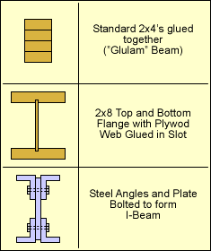
 Typical Built-up Beams |
Built-up Members |
|
|
This section does not introduce any new equations, but instead deals with how to use the shear stress equation in designing beams made from various smaller structural members. By using smaller members, beams can be customized for strength and sometimes for visual appeal. Two common wood build-up members is stacked lumber, such as 2x4's. Wood can be easily glued and modern adhesives are extremely strong (stronger than wood in most cases). Structural steel members are usual bolted or welded together. This can be labor intensive and thus not as common as built-up wood beams. |
||
| Built-up Beams Using Adhesives |
||
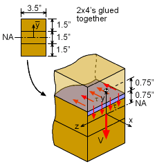
 Shear Stress at Adhesive Joint of Glulam Beam. |
Since adhesive is applied evenly (hopefully) over the surface, the shear stress only needs to be less than the allowable shear stress of the adhesive. For example, if three 2x4's are glued together to form a new built-up beam (commonly referred to as a "Glulam" beam, short for glued laminated beam), then the shear stress at the joints should be determined. The shear stress can be calculated for either joint (will be the same due to symmetry) using the shear stress equation presented previously. Assuming V = 10 kip, the shear stress in the adhesive will be = 0.8465 ksi |
|
| Built-up Beams Using Bolts, Nails, Screws, Rivets, etc. |
||
|
|
Unlike adhesive joints, bolts, nails, screws, and rivets (attachment devices) are not continuous. Thus, the shear stress needs to be converted to a single load over a given area. Then that load needs to be applied to the attachment device. This can be confusing since spacing and location of a given attachment device may not be known. In fact, the design of built-up beams require the designer to specify the spacing and location of the attachment devices. |
|
 Shear Load in an Example of a Bolted Built-up Beam |
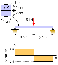
The best way to understand the design of built-up members using attachment devices is to examine a typical example. Assume a simple support beam is constructed from two simple steel bars, each 4 cm by 2 cm as shown in the diagram. The two bars are bolted together with 8 mm diameter steel bolts. There is a simple center load of 5 kN. Assume the steel can withstand 125 MPa shear stress (both the bolts and bars). What should be the space between the bolts along the length of the beam? First, construct a shear diagram to find the maximum shear load. In this case, the shear load magnitude is constant at 2.5 kN. Next, determine the actual shear stress at the joint using the basic shear stress equations, where I and Q are I = 0.04 (0.04)3 / 12 = 2.133 × 10⁻⁷ m4 This gives |
|
 Single Bolt Section |
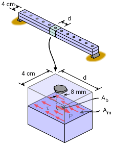
This shear stress, τ, between the members must be carried by the bolts that are spaced at a distance d. Thus, the shear stress over a distance d must be carried by one bolt, as shown in the diagram. The total load, F, from the shear stress over the area Am will be F = τ Am = (2.344 MPa) (0.04 m) d = (93.76 d) kN This load must be carried by the bolt. The allowable shear stress in the bolt, τa is only 125 MPa. The total bolt load will be P = τa Ab = (125 MPa) [π(0.004 m)2] = 6.283 kN Since P and F must be equal, F = P 93.76 d = 6.283 d = 0.06701 m = 6.701 cm In other cases, the bolt size may be unknown, but the spacing given. It is important to remember that the shear stress must be carried by the bolt (or nail, screw, rivet, etc.) or an adhesive. |
|
Practice Homework and Test problems now available in the 'Eng Mechanics' mobile app
Includes over 500 free problems with complete detailed solutions.
Available at the Google Play Store and Apple App Store.

