| Ch 4. Beam Stresses | Multimedia Engineering Mechanics | ||||||
|
Bending Strain and Stress |
Beam Design |
Shear Stress |
Built-up Beams |
||||
| Shear Stress | Case Intro | Theory | Case Solution | Example |
| Chapter |
| 1. Stress/Strain |
| 2. Torsion |
| 3. Beam Shr/Moment |
| 4. Beam Stresses |
| 5. Beam Deflections |
| 6. Beam-Advanced |
| 7. Stress Analysis |
| 8. Strain Analysis |
| 9. Columns |
| Appendix |
| Basic Math |
| Units |
| Basic Mechanics Eqs |
| Sections |
| Material Properties |
| Structural Shapes |
| Beam Equations |
| eBooks |
| Dynamics |
| Fluids |
| Math |
| Mechanics |
| Statics |
| Thermodynamics |
| ©Kurt Gramoll |
|
|
||||||||
 Beam without Adhesion Between Layers |
Although bending stress is generally the primary stress in beams, shear stress can also be critical in short beams. Shear stress occurs in all beams with bending moments and it tries to slide one horizontal beam section across another. For example, a cantilever beam constructed with non-attached layers, as shown at the left, will slide. If the beam is one unit, then the internal shear stress will try to slide the attached layers. This effect can cause beams to split in the horizontal direction. |
|||||||
 Shear Stress on a Horizontal Plane |
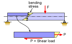
Another way to grasp how shear stress acts on a beam is to take a small horizontal section and sum the forces. For example, the horizontal section shown in the diagram at the left must be in static equilibrium. At the left end, there is no force since it is a free surface. The right side has a force, P, equal to the total of the normal bending stress at that surface. For the section to be equilibrium, there must be a force acting to the left to counter the bending stress load. This is the shear stress acting in the horizontal direction. It will vary at different locations. |
|||||||
| Horizontal Shear Stress |
||||||||
 Small Slice of Beam |
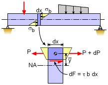
The first step in determining the shear stress at any location is to look at a section in a small slice from the beam. Summing the forces due to the normal bending stresses in the horizontal direction gives ΣFx = 0 - P + (P + dP) + τ b dx = 0 -dP/dx = τ b (1) where b is the beam depth at the location of the shear stress being calculated. Note, P is assumed to be in tension (positive) for derivation. |
|||||||
 Equivalent Systems |
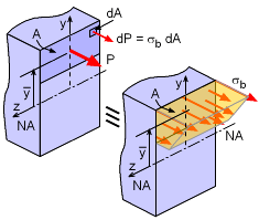
P can be found by integrating the normal stress over a section A (shown in diagram), giving But the bending stress is σb = -My/I. Substituting and simplifying gives Since M and I do not change, they can be moved outside the integral. |
|||||||
|
The integral now is just the first moment of the area that is commonly used to find the centroid of an area, and is called "Q". Substituting P into the equation (1) and using Q, gives Recall, the derivative, dM/dx is equal to the vertical shear load V. This gives, The final horizontal shear stress equation is
|
||||||||
| Calculating Q |
||||||||
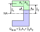 Determining Q by Parts at Section a-a |
One of the confusing aspects of determining the shear stress τ, is calculating Q, the first moment of the area about the neutral axis. It is rare when the full integral, is needed. Generally, Q can be determined using parts which is can be written as
|
|||||||
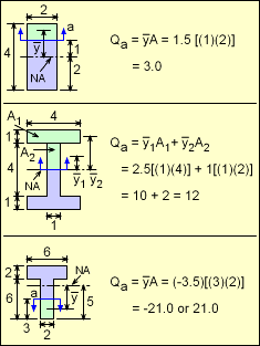 Examples of Q at line a for various shapes (Q units are distance cubed) |
In determining Q, there are a number of steps that should be considered:
Examples of Q for various shapes and stress locations are given at the left. Note, Q can be negative, but the shear stress equation assume all positive values. |
|||||||
| Vertical Shear Stress |
||||||||
|
|
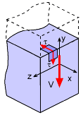
Shear stress acts on two different parallel surfaces of any element as shown in the diagram at the left. One side cannot be under a different shear stress magnitude than the other. If a small element is taken from a structure under shear, parallel sides will have shear stress loading in the opposite direction, causing it to shear as shown in the diagram at the left. Notice, the other two sides try to resist the sliding motion, and the stress element stays in equilibrium. Similarly, a small element taken from a beam under a shear loading will have equal shear stresses in the vertical and horizontal directions as shown in the diagram at the left. The magnitude of the shear stress will depend on the location of the stress element. There are three possible shear stresses on a three dimensional cube. This section has only examined one dimension since shear loading in beams is generally only in one direction. But just like uniaxial loading, shear loading can be in three directions. |
|||||||
| Rectangular Beams |
||||||||
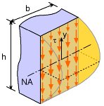 Shear Stress Distribution in Rectangular Beam |
Rectangular beams are so common, it is helpful to plot the shear stress from top to bottom. The resulting equation is
It is a parabolic shape with the maximum at the center. The center shear stress is
|
|||||||


