| Ch 3. Beam Shear/Moment Diagrams | Multimedia Engineering Mechanics | ||||||
|
Shear and Moment |
Shear/Moment Diagrams |
Moving Loads |
|||||
| Shear and Moment in Beams | Case Intro | Theory | Case Solution | Example |
| Chapter |
| 1. Stress/Strain |
| 2. Torsion |
| 3. Beam Shr/Moment |
| 4. Beam Stresses |
| 5. Beam Deflections |
| 6. Beam-Advanced |
| 7. Stress Analysis |
| 8. Strain Analysis |
| 9. Columns |
| Appendix |
| Basic Math |
| Units |
| Basic Mechanics Eqs |
| Sections |
| Material Properties |
| Structural Shapes |
| Beam Equations |
| eBooks |
| Dynamics |
| Fluids |
| Math |
| Mechanics |
| Statics |
| Thermodynamics |
| ©Kurt Gramoll |
|
|
|||||
|
It is important to understand, and be able to find, the internal moments, shear force and axial force at any point in a beam structure. These values can then be used to help design the beam. In this section, the internal loads (moment, shear and axial) will be calculated for a specific location. The next section will expand this concept, and develop diagrams showing the internals at all locations. Before the internal loads are determined, a few topics need to be reviewed, specifically, equilibrium equations, boundary conditions, and load types. |
|||||
| Static Equilibrium Equations |
|||||
|
|
Determining internal loads of beam structures requires a good understanding of static equilibrium equations and how to apply boundary conditions. For any static equilibrium problem, all forces and moments in all directions must be equal to zero. This is summarized in equation form as
Most situations require only the 2D form of these equations, or ΣFx = 0 ΣFy = 0 ΣMz = 0 |
||||
| Boundary Conditions |
|||||
 Typical Boundary Conditions |
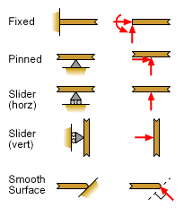
For typical 2D problems, there are three basic types of boundary conditions, fixed, pinned and slider (includes smooth surface). All three have different reaction forces that need to be used when the support is removed as illustrated in the diagram at the left. The Fixed condition has three reactions (2 force and 1 moment) since it cannot rotate, nor displace in either direction. The Pinned condition cannot displace but it can freely rotate. This requires only two reaction forces. The Slider condition allows the member to move in only one direction but it can freely rotate. This means there is only one reaction force perpendicular to the direction of the motion. A special case is when there is a smooth surface without friction. This allows the member to freely slide in the direction of the slope. The diagram uses triangular shapes to represent pinned connections. The triangle vertex is the pin location. When it is sliding, the triangle has two rollers to indicate free motion along the surface. Note that the rollers DO NOT indicate the member can lift off the surface, only sliding motion. |
||||
| Types of Loads |
|||||
|
|
|
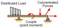
Several types of loads can act on beams, such as concentrated loads, distributed loads, and couples. Concentrated loads are idealized from loads applied on a very small area. Distributed loads are spread along the axes of beams. For example, the weight of the beam can be assumed as a distributed force. Couples are moments applied on the beam. |
|||
|
|
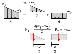
Generally, distributed loads are converted into equivalent forces to make the solution process easier. For vertical loads, the equivalent force is The location of the equivalent load is found by
|
||||
 Example: Equivalent Loads for Uniform Distributed Load |
|||||
|
As illustrated in the example at the left, distributed loads can be split into separate distributed load. This makes finding the total equivalent force easier without doing the actual integration. The location of the equivalent force is through the centroid of the distributed load. Thus, if the distributed load is a basic shape, the centroid is easy to determine without integration. In fact, most basic shapes are listed in handbook tables (see Sections Appendix). |
|||||
| Sign Conventions |
|||||
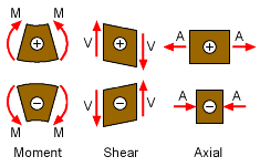 Sign Conventions for Bending Moments, Shear Forces and Axial Forces |
The sign convention for shear forces and bending moments are not based on their directions along the coordinates axes. The positive bending moment tends to compress the upper part of the beam and elongate the lower part. The negative bending moment tends to elongate the upper part of the beam and compress the lower part of the beam. The positive shear force tends to rotate the material clockwise. The negative shear force tends to rotate the material counterclockwise. And the positive axial force tends to pull the material apart where as the negative force compresses the material. | ||||
| Internal Moments and Forces |
|||||
|
|
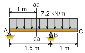
The first step in finding the internal loads (moment, shear force, and axial force) at a point is to determine the reactions at all supports. This is done by using the three equilibrium equations. To assist in this task, equivalent forces replace the distributed loads, as shown in the example at the left. Then, the basic equations give, ΣMA =
0 ΣFy =
0 |
||||
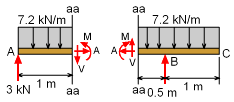 Beam is Cut, and Internal Loads (M,V, and A) Replace the Removed Section |
After the reaction forces are known, the structure is cut at the location where the internal loads need to be determined. In the example at the left, this is at the section aa line. In order to maintain a segment of a beam in equilibrium, there exists an internal vertical force V at the cut to satisfy the equation in the y-direction. This internal force, which is vertical to the axis of the beam, is called the shearing force. It should be noted that the same shear is opposite in direction in the left and right sections. |
||||
|
|
Similarly, there exists an internal resisting moment M at the cut to keep a segment of the beam in equilibrium. This internal moment acts in a direction opposite to the external moment to satisfy the moment equation. Sign convention is important at this point. The unknown internal loads should be drawn as positive loads. Remember, the left and right sections have opposite positive directions. If the two sections were joined again, M, V, and A internal loads need to cancel out since there is no external resultant force at cut location. |
||||
|
|
The internal loads can now be determined by analyzing either beam section using the basic equilibrium equations. There are three unknowns, M, V, and A, and there are there equations, ΣFx = 0 |
||||
|
Applying these three equations give, A = 0 The moment in this example is positive, so the assumed internal moment direction was correct. However, the shear force is negative so the actual shear force is opposite to the direction assumed in the diagram. |
|||||
Practice Homework and Test problems now available in the 'Eng Mechanics' mobile app
Includes over 500 free problems with complete detailed solutions.
Available at the Google Play Store and Apple App Store.

