| Ch 2. Torsion | Multimedia Engineering Mechanics | ||||||
|
Circular Bars |
Nonuniform & Indeterminate |
Thin-walled Tubes |
Non-Circular Bars | ||||
| Nonuniform & Indeterminate Torsion | Case Intro | Theory | Case Solution | Example |
| Chapter |
| 1. Stress/Strain |
| 2. Torsion |
| 3. Beam Shr/Moment |
| 4. Beam Stresses |
| 5. Beam Deflections |
| 6. Beam-Advanced |
| 7. Stress Analysis |
| 8. Strain Analysis |
| 9. Columns |
| Appendix |
| Basic Math |
| Units |
| Basic Mechanics Eqs |
| Sections |
| Material Properties |
| Structural Shapes |
| Beam Equations |
| eBooks |
| Dynamics |
| Fluids |
| Math |
| Mechanics |
| Statics |
| Thermodynamics |
| ©Kurt Gramoll |
|
|
|||||
| Nonuniform Torsion |
|||||
|
|
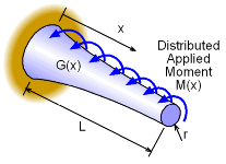
In the previous section on circular bars and shafts, the bar cross section, internal moment, and stiffness was assumed to be constant. This simplified the process of finding the angle of twist. The total angle of twist for a shaft could be found by summing smaller segments of the shaft, giving If the segments are reduced to infinitesimal length, dx, then the summation can be replaced with an integral, giving
where T(x) is the internal moment function, G(x) is a function describing the changing stiffness, and J(x) is a function based on the cross section (changing radius). The bar or shaft is still assumed to be circular. It is important to note the applied moment, M(x) is not the same as the internal moment, T(x). However, T(x) can be determined from applied moment and boundary conditions. If T, G, and J are all simultaneously functions of x, the integral can be extremely complex and a closed form solution may not be possible. In those cases, numerical solution techniques are required. In general, the internal moment is the most common parameter that will vary. A good example is a drill where the moment builds up as the shaft goes deeper into the material (oil drilling, screw, etc.). |
||||
| Indeterminate Structures - Torsion |
|||||
|
|
Similar to axial structures, torsional shafts can have redundant boundary conditions or supports. When the moment or torque in a shaft (or set of shafts) cannot be determined with the basic summation of moments equation (ΣM = 0), then some type of compatibility equations must be used. Compatibility equations relate deflections or strains in a structure. Generally, deflections are the easiest type of compatibility. For example, for two concentric shafts, the angle of twist between them must be equal. On the other hand, two shafts that are connected by gears or belts must have the arc length rotation equal. |
||||
 Indeterminate Structure: Concentric Shafts |
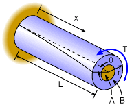
There is no single compatibility equation that will work for all indeterminate torsion structures. This makes it difficult and requires the engineer to understand the deflection process. However, two common compatibility relationships are given in the two diagrams at the left. The first type is two or more concentric shafts. Assuming the shafts are attached (no slipping) the angle of twist must be the same for all shafts. For two shafts, labeled as A and B in the diagram at the left, the angle of twist needs to be equal. θA = θB |
||||
 Indeterminate Structure: Gear Shafts |
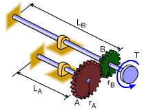
Another typical indeterminate torsion structure is two separate shafts that are connect through a set of gears at one end and fixed at the other. Each shaft will take some of the applied torque (or moment) but the exact distribution cannot be found with just static equilibrium equations. Unlike the concentric shafts mentioned previously, the angle of twist between the shafts will not be equal. However, they are related since the gears cannot slip. The arc length change in both gears will be the same. Thus, the compatibility equation will be, θA rA = θB rB |
||||
| It needs to be noted again, there is no single compatibility equation. Each problem and structure will have its own compatibility that must be identified and modeled as an equation. The previous two examples are only examples and the actual compatibility equation may be different. | |||||
Practice Homework and Test problems now available in the 'Eng Mechanics' mobile app
Includes over 500 free problems with complete detailed solutions.
Available at the Google Play Store and Apple App Store.
