| Ch 10. Rankine Cycle | Multimedia Engineering Thermodynamics | ||||||
|
Rankine Cycle |
Reheat | Regeneration | Cogeneration | ||||
| Ideal Cogeneration Rankine Cycle | Case Intro | Theory | Case Solution |
| Chapter |
| 1. Basics |
| 2. Pure Substances |
| 3. First Law |
| 4. Energy Analysis |
| 5. Second Law |
| 6. Entropy |
| 7. Exergy Analysis |
| 8. Gas Power Cyc |
| 9. Brayton Cycle |
| 10. Rankine Cycle |
| Appendix |
| Basic Math |
| Units |
| Thermo Tables |
| Search |
| eBooks |
| Dynamics |
| Fluids |
| Math |
| Mechanics |
| Statics |
| Thermodynamics |
| Author(s): |
| Meirong Huang |
| Kurt Gramoll |
| ©Kurt Gramoll |
|
|
||
|
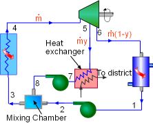
A cogeneration power plant is used to generate power as well as supply heat for a district heating system. The mass flow in the cycle and the utilization factor are needed to be determined. Assumptions:
|
||
|
|
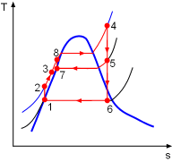
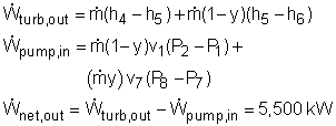
Model the cycle as an ideal cogeneration Rankine cycle. The schematic of the cogeneration power plant and its T-s diagram are shown on the left. (1) Determine the mass flow rate in the cycle Assume the mass flow rate in the cycle is The community needs 1,100 kW heat from the power plant. Since the heat exchanger has a 85% efficiency, the energy balance of the heat exchanger is, Also, the net work output from the cycle is 5,500 kW.
|
|
|
Saturated
Water Temperature Table Saturated Water Pressure Table Superheated Steam Table |
All the enthalpies at state 1 to state 6 can be obtained from the water
tables. Then solving the above equations simultaneously can get the mass
flow rate State1: saturated water State 2: compressed water State 5: superheated vapor State 6: saturated mixture State 7: saturated water State 8: compressed water Substituting the enthalpies to the above equations and solving for |
|
(2) the utilization factor of the cogeneration plant The definition of the utilization factor of the cogeneration plant is Net work output from the power plant is given as 5,500 kW. The process heat is: Before determine the total heat input, the enthalpy at state 3 needs to be obtained first. Water at state 2 and state 8 mixes in the mixing chamber at constant pressure. The energy balance of the mixing chamber is The total heat input to the cycle is Hence, the utilization factor of the cogeneration plant is εu = (5,500+1,294.1)/(13,644) = 49.8% |
||


