| Ch 9. Brayton Cycle | Multimedia Engineering Thermodynamics | ||||||
|
Brayton Cycle |
Intercooling and Reheating |
||||||
| Brayton Cycle with Intercooling | Case Intro | Theory | Case Solution |
| Chapter |
| 1. Basics |
| 2. Pure Substances |
| 3. First Law |
| 4. Energy Analysis |
| 5. Second Law |
| 6. Entropy |
| 7. Exergy Analysis |
| 8. Gas Power Cyc |
| 9. Brayton Cycle |
| 10. Rankine Cycle |
| Appendix |
| Basic Math |
| Units |
| Thermo Tables |
| Search |
| eBooks |
| Dynamics |
| Fluids |
| Math |
| Mechanics |
| Statics |
| Thermodynamics |
| Author(s): |
| Meirong Huang |
| Kurt Gramoll |
| ©Kurt Gramoll |
| |
||
Thermodynamic cycles can be divided into two general categories: power cycles, which produce a net power output, and refrigeration and heat pump cycles, which consume a net power input. The thermodynamic power cycles can be categorized as gas cycles and vapor cycles. In gas cycles, the working fluid remains in the gas phase throughout the entire cycle. In vapor cycles, the working fluid exits as a vapor during one part of the cycle and as a liquid during another part of the cycle. Internal combustion engines and gas turbines undergo gas power cycle. The two major application areas of gas-turbine engines are aircraft propulsion and electric power generation. This section will introduce the ideal cycle for gas-turbine engine - Brayton cycle with intercooling, reheating, and regeneration. |
||
| The Brayton Cycle with Regeneration
|
||
|
|
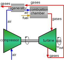
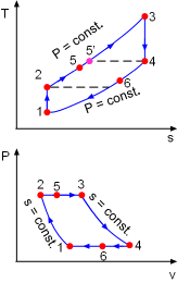
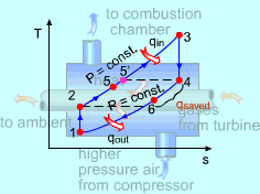
In gas-turbine engines, if the temperature of the exhaust gases from the turbine is higher than the temperature of the air leaving the compressor, a counter-flow heat exchanger can be used to increase the temperature of the air by receiving heat from the exhausted gases, and the counter-flow heat exchanger is called a regenerator or a recuperator. The thermal efficiency of the Brayton cycle can be increased since the energy in the exhaust gases is used as a portion of the heat input and save fuel requirements for the same net work output. The T-s and P-v diagrams of an ideal Brayton cycle with regeneration is shown on the left. Air increases its temperature from T2 to T5 and the exhausted gases decrease their temperature from T4 to T6 in the regenerator. In an actual case, T5 is less than T4 and T6 is larger than T2. Heat transferred from the exhausted gases to the air is qregen, act = h5 - h2 In the ideal situation, air leaves the regenerator at the same temperature of the inlet exhausted gases (T4), denoted as T5'. Now the heat transferred from the exhausted gases to the air becomes qregen, max = h5' - h2 = h4 - h2 The ratio of the actual heat transferred from the exhausted gases to the air to the maximum heat transferred from the exhausted gases to the air is called effectiveness (ε). ε = (h5 - h2)/(h4 - h2) The effectiveness of most regenerators used in practice is below 0.85. Under cold-air-assumption, the thermal efficiency of an ideal Brayton cycle with regeneration is |
|
| The Brayton Cycle with Intercooling, Reheating, and
Regeneration
| ||
 Compressors with Intercooling |
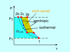
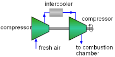
The net work output from a gas-turbine is the difference of the work generated by the turbine and the work consumed by the compressor. The net work output can be increased by either decreasing the compressor work or increasing the turbine work, or both. Using multistage compression with intercooling can decrease the compressor work. This can be shown by the following case. Assume a compressor needs to compress gas from P1 to P2. Three methods are available.
|
|
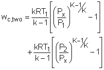
The compressor works of the three processes are: Isentropic: Two-stage: |
||
|
|
The three processes are plotted on a P-v diagram shown on the left. On a P-v diagram, the area to the left of the process curve is the integral of vdP. This is a measure of the steady-flow compression work. One can observe from this diagram that isentropic compression requires the maximum work, the isothermal compression requires the minimum, and two-stage isentropic compression is between. In practice, it is not possible to compress gas in an isothermal manner. So a technique called multistage compression with intercooling, where the gas is compressed in stages and cooled in between each stage to its initial temperature by passing it through a heat exchanger, is used. This heat exchanger is called an intercooler. The two-stage compression illustrated above is a simple case of multistage compression. Its compressor work varies with Px. When Px satisfied the following condition, the compressor work achieves its minimum. |
|
Likewise, the work output from a turbine can be increased by expanding the gas in stages and reheating it in between. This technique is called multistage expansion with reheating. Combustion in gas turbines typically occurs at four times the amount of air needed for complete combustion. Therefore, reheating can be accomplished by simply spraying additional fuel into the exhaust gases between two expansion states. For two-stage expansion, similar with two-stage compression, the turbine work output reaches its maximum when equal pressure ratios are maintained across each stage. When intercooling and reheating are used, the working fluid leaves the turbine at a higher temperature and the compressor at a lower temperature. This makes regeneration more attractive. |
||
