| Ch 9. Brayton Cycle | Multimedia Engineering Thermodynamics | ||||||
|
Brayton Cycle |
Intercooling and Reheating |
||||||
| Brayton Cycle | Case Intro | Theory | Case Solution |
| Chapter |
| 1. Basics |
| 2. Pure Substances |
| 3. First Law |
| 4. Energy Analysis |
| 5. Second Law |
| 6. Entropy |
| 7. Exergy Analysis |
| 8. Gas Power Cyc |
| 9. Brayton Cycle |
| 10. Rankine Cycle |
| Appendix |
| Basic Math |
| Units |
| Thermo Tables |
| Search |
| eBooks |
| Dynamics |
| Fluids |
| Math |
| Mechanics |
| Statics |
| Thermodynamics |
| Author(s): |
| Meirong Huang |
| Kurt Gramoll |
| ©Kurt Gramoll |
| |
||
Thermodynamic cycles can be divided into two general categories: power cycles, which produce a net power output, and refrigeration and heat pump cycles, which consume a net power input. The thermodynamic power cycles can be categorized as gas cycles and vapor cycles. In gas cycles, the working fluid remains in the gas phase throughout the entire cycle. In vapor cycles, the working fluid exits as a vapor during one part of the cycle and as a liquid during another part of the cycle. Internal combustion engines and gas turbines undergo gas power cycle. The two major application areas of gas-turbine engines are aircraft
propulsion and electric power generation. This section introduces
the ideal cycle for gas-turbine engine
- Brayton cycle and jet-propulsion cycle for aircraft propulsion. |
||
| Brayton cycle - the Ideal Cycle for Gas-turbine
Engine
|
||
|
|
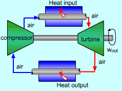
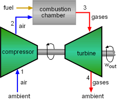
Gas-turbines usually operate on an open cycle, shown on the left.
Part of the work generated by the turbine is sent to drive the compressor.
The fraction of the turbine work used to drive the compressor is called the back work ratio. |
|
 The Ideal Brayton Cycle |
Since fresh air enters the compressor at the beginning and exhaust are thrown out at the end, this cycle is an open cycle. By utilizing the air-standard assumptions, replacing the combustion process by a constant pressure heat addition process, and replacing the exhaust discharging process by a constant pressure heat rejection process, the open cycle described above can be modeled as a closed cycle, called ideal Brayton cycle. The ideal Brayton cycle is made up of four internally reversible processes.
|
|
 P-v and T-s Diagrams of Ideal Brayton Cycle |
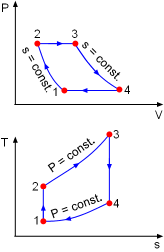
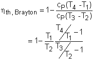
The P-v and T-s diagrams of an ideal Brayton cycle are shown on the left. In an ideal Brayton cycle, heat is added to the cycle at a constant pressure process (process 2-3). qin = h3 - h2 = cP(T3 - T2) Heat is rejected at a constant pressure process (process 4 -1). qout = h4 - h1 = cP(T4 - T1) Then the thermal efficiency of the ideal Brayton cycle under the cold air-standard assumption is given as
|
|
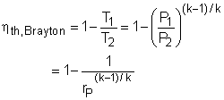
Process 1-2 and process 3-4 are isentropic processes, thus, Since P2 = P3 and P4 = P1, Considering all the relations above, the thermal efficiency becomes, where rP = P2/P1 is the pressure ratio and k is the specific heat ratio. In most designs,
the pressure ratio of gas turbines range from about 11 to 16. |
||
| Actual Gas-turbine Cycle
|
||
 T-s Diagram of Actual Gas-turbine Cycle |
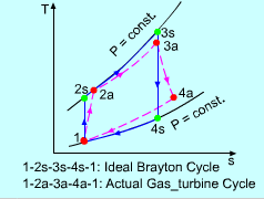
The actual gas-turbine cycle is different from the ideal Brayton cycle since there are irreversibilities. Hence, in an actual gas-turbine cycle, the compressor consumes more work and the turbine produces less work than that of the ideal Brayton cycle. The irreversibilities in an actual compressor and an actual turbine can be considered by using the adiabatic efficiencies of the compressor and turbine. They are: Another difference between the actual Brayton cycle and the ideal cycle is that there are pressure drops in the heat addition and heat rejection processes. |
|
| Gas-
Turbines for Aircraft Propulsion
|
||
Gas-turbines are widely used to power aircraft. Aircraft gas turbines operate on an open cycle called a jet-propulsion cycle. Jet-propulsion cycle differs from the Brayton cycle in the gas expansion process. In Brayton cycle, gases are expanded to ambient conditions, but in jet-propulsion cycle, the gases are expanded to a pressure such that the power produced is only enough to drive the compressor and the auxiliary equipment. Therefore, the net work output of a jet-propulsion cycle is zero. The high pressure gases exit from the turbine are sent to a nozzle. They are accelerated in the nozzle to provide the thrust to propel the aircraft. Also, aircraft gas turbines operate at higher pressure ratios (between 10 and 25). To get a high pressure before the compression process, the fluid passes through a diffuser first. |
||
|
|
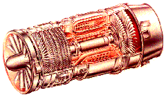
Aircraft are propelled by accelerating a fluid in the opposite direction to motion. Propeller-driven engine accomplishes this by slightly accelerating a large mass of fluid, jet or turbojet accomplishes this by greatly accelerating a small mass of fluid, and turboprop engine uses both. In a turbojet engine, the cycle proceeds as follows,
|
|
|
|
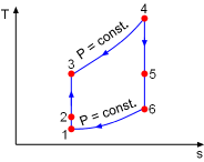
In an ideal jet-propulsion cycle, the power generated in the turbine equals the power consumed in the compressor. And the processes in the diffuser, compressor, turbine and nozzle are assumed to be isentropic. The T-s diagram is shown on the left. The thrust force developed in a turbine engine can be determined from Newton's second law. According to the Newton's second law, the thrust produced by the jet engine is equal to the rate of change of the momentum of the fluid flowing through the engine. When the inlet and exit pressures of the engine are identical, the thrust force is |
|
|
where Propulsive power ( The efficiency of a turbojet engine is defined through the general definition since the net work output is zero. The desired output in a turbojet engine is the propulsive power and the required input is the thermal energy of the fuel released in the combustion process. This efficiency is called the propulsive efficiency. The propulsive efficiency measures how much energy released in the combustion process is converted to propulsive energy. |
||


 A
Turbojet Engine