| Ch 8. Gas Power Cycle | Multimedia Engineering Thermodynamics | ||||||
|
Otto Cycle |
Diesel Cycle |
||||||
| Diesel Cycle | Case Intro | Theory | Case Solution |
| Chapter |
| 1. Basics |
| 2. Pure Substances |
| 3. First Law |
| 4. Energy Analysis |
| 5. Second Law |
| 6. Entropy |
| 7. Exergy Analysis |
| 8. Gas Power Cyc |
| 9. Brayton Cycle |
| 10. Rankine Cycle |
| Appendix |
| Basic Math |
| Units |
| Thermo Tables |
| Search |
| eBooks |
| Dynamics |
| Fluids |
| Math |
| Mechanics |
| Statics |
| Thermodynamics |
| Author(s): |
| Meirong Huang |
| Kurt Gramoll |
| ©Kurt Gramoll |
|
|
||
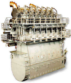 An CI Engine Used in Ships |
Thermodynamic cycles can be divided into two general categories: power cycles, which produce a net power output, and refrigeration and heat pump cycles, which consume a net power input. The thermodynamic power cycles can be categorized as gas cycles and vapor cycles. In gas cycles, the working fluid remains in the gas phase throughout the entire cycle. In vapor cycles, the working fluid exits as vapor phase during one part of the cycle and as liquid phase during another part of the cycle. Internal combustion engines and gas turbines undergo gas power cycle. Internal combustion engines, which are commonly used in automobiles, have two principal types: spark-ignition engines and compression-ignition engines. This section will introduce the compression-ignition engines and the ideal cycle for compression-ignition engines - Diesel Cycle. |
|
| Four-stroke Compression-ignition (CI)
engine
|
||
|
|
In compression-ignition engines, air is compressed to a high pressure and temperature which is above the auto ignition temperature of the fuel. When the fuel is injected, the combustion occurs spontaneously. Compression-ignition engines are suited for heavy trucks, buses, and ships which require large amount of power. In spark-ignition engine, compression ratio is limited because of engine knock. In CI engine, only air is compressed during the compression stroke. Therefore, CI engine can be designed to operate at a much higher compression ratio. The four strokes for a CI engine is the same as SI engine. They are
A new cycle can begin again. |
|
| Diesel Cycle - Ideal Cycle for Compression-ignition
Engines
|
||
|
|
The only difference between ideal Otto cycle and ideal Diesel cycle is the heat addition process. Instead of constant volume heat addition process in SI engine, heat is added to the air in the Diesel engine at constant pressure. The four processes are:
|
|
 Constant Pressure Heat Addition (2-3)
|
Noting that the ideal Diesel cycle is executed in a closed system and the working fluid is air according to the air-standard assumption. Also, changes in kinetic and potential energies are negligible. No heat transfer is involved in the two isentropic processes. The energy balances for these two processes are: -w12 = u2 - u1 -w34 = u4 - u3 w12 is negative since work is needed to compress the air in the cylinder and w34 is positive since air does work to the surroundings during its expansion. In the constant pressure heat addition process, air is expanded to keep the pressure as constant during the heat addition. The expansion work equals w23 = P2(v3 - v2) The energy balances for this process is: q23 = u3 - u2 + w23 = h3 - h2 In the constant volume heat rejection process, no work interaction is involved since no volume change occurs. The energy balances for this process is: q41 = u1 - u4 q23 is positive since heat is added to the air and q41 is negative since heat is rejected to the surroundings during this process. For the whole cycle, the energy balance can be determined by adding the energy balance of its four processes. That is, q23 + q41 - w12 - w34 = 0 |
|
The thermal efficiency of an ideal Otto cycle is ηth,Diesel = wnet/qin According to the analysis above, the net work output is wnet = w34 + w12 = q23 + q41 qin = q23 ηth, Diesel = 1+ q41/q23 Under the cold air-standard assumption, the thermal efficiency of an ideal Diesel cycle is |
||
In order to simplify the above equation, the cutoff ratio rc is defined as rc = v3/v2 Process 1-2 and process 3-4 are isentropic. Thus, The thermal efficiency relation reduces to |
||