| Ch 3. Beam Shear/Moment Diagrams | Multimedia Engineering Mechanics | ||||||
|
Shear and Moment |
Shear/Moment Diagrams |
Moving Loads |
|||||
| Shear and Moment in Beams | Case Intro | Theory | Case Solution | Example |
| Chapter |
| 1. Stress/Strain |
| 2. Torsion |
| 3. Beam Shr/Moment |
| 4. Beam Stresses |
| 5. Beam Deflections |
| 6. Beam-Advanced |
| 7. Stress Analysis |
| 8. Strain Analysis |
| 9. Columns |
| Appendix |
| Basic Math |
| Units |
| Basic Equations |
| Sections |
| Material Properties |
| Structural Shapes |
| Beam Equations |
| Search |
| eBooks |
| Dynamics |
| Fluids |
| Math |
| Mechanics |
| Statics |
| Thermodynamics |
| Author(s): |
| Kurt Gramoll |
| ©Kurt Gramoll |
|
|
||
|
|
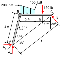
A four foot folding ladder is being considered for a work platform on a sloping roof. The roof angle is 38 degrees and the ladder needs to be horizontal when placed on the roof as shown in the free-body-diagram (FBD) at the left. There are two loads on the ladder, the person working and the roofing materials. The person is a concentrated force of 150 lb and the materials is a distributed force ranging from 200 to 100 lb/ft. The location of both are indicated in the diagram. The total moment, shear force and axial force on the top member of the ladder needs to be determined at a location just to the right of the joint. Distance 's' can be determined from the Law of the Cosines, s2 = 42 + 42 - 2(4)(4) cos 104 |
|
| Equivalent Loads |
||
|
|
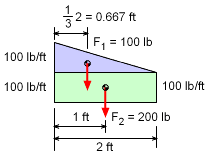
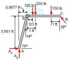
The distributed load can be converted into two concentrated loads which will simplify the solution process. The two equivalent loads are, F1 = 0.5 (2 ft) (100 lb/ft) = 100 lb (triangle area) F2 = (2 ft) (100 lb/ft) = 200 lb (rectangle area) The location of each concentrated load is at the centroid of their area. For the triangle, it is (1/3)2 = 2/3 ft from the left edge. The revised FBD, reflecting the new equivalent forces, is shown at the left. Important angles and distances are also shown on the diagram. The vertical and horizontal distance between points A and B can be determined as (AB)x = 4 sin14 = 0.9677 ft (AB)y= 4 cos14 = 3.881 ft |
|
| Reactions |
||
|
Before the internal loads can be determined, the external reactions need to be found. In this case, there are three unknowns, so the three equilibrium equations for 2D can be applied to give, ΣMA = 0
ΣFy = 0
ΣFx = 0
|
||
| Section Cut at Specified Location |
||
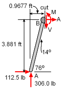 FBD of Left Section |
The problem asks for the moment, M, shear, V, and axial load, A, just left of the middle joint, B. This can be done by cutting the ladder at that location and analyzing either the left or right section. The FBD of the left section is shown at the left. This section must be in static equilibrium, just like the full structure. Thus, the three equilibrium equations can be used to solve for the three unknowns, M, V, and A. ΣFx = 0 ΣFy =
0 ΣMcut =
0 |
|
| Alternate Solution Method - Check |
||
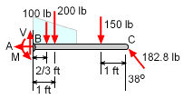 FBD of Right Section |
As mentioned previously, either side of the cut can be used to determine the moment, M, shear, V, and axial load, A. As a check, the right section will now be analyzed and compared to the previous solution. Of course, the two solutions should match but many times they do not due to calculation errors. The FBD of the right section is shown at the left. Notice, the loads M, V, and A are in the opposite direction as the previous analysis since the opposite section is used. Summing the forces and the moments give, ΣFx = 0 ΣFy = 0 ΣMcut =
0 Notice, all three values match the previous calculations, as they should. |
|
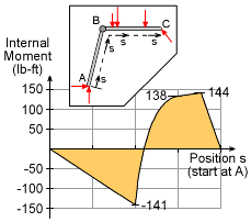 Internal Moment of Ladder as a Function of Location |
Change in Moment Across Ladder |
|
|
While not requested in this case, it is interesting to visualize the change in internal moment if the cut was moved to other locations. The graph at the left indicates the internal moment magnitude as a function of the cut location, s. The starting point is at A, then goes to B and then to C. Notice the maximum is not at joint B, but at the point where the person is standing. However, joint C does have a large moment and since it is a joint, it would probably fail before the straight section where the person is standing. |
||
Practice Homework and Test problems now available in the 'Eng Mechanics' mobile app
Includes over 500 free problems with complete detailed solutions.
Available at the Google Play Store and Apple App Store.
