| Ch 10. Open-Channel Flow | Multimedia Engineering Fluids | ||||||
|
Uniform Flow |
Gradually Varied Flow |
Rapidly Varied Flow |
|||||
| Gradually Varied Flow | Case Intro | Theory | Case Solution |
| Chapter |
| 1. Basics |
| 2. Fluid Statics |
| 3. Kinematics |
| 4. Laws (Integral) |
| 5. Laws (Diff.) |
| 6. Modeling/Similitude |
| 7. Inviscid |
| 8. Viscous |
| 9. External Flow |
| 10. Open-Channel |
| Appendix |
| Basic Math |
| Units |
| Basic Equations |
| Water/Air Tables |
| Sections |
| Search |
| eBooks |
| Dynamics |
| Fluids |
| Math |
| Mechanics |
| Statics |
| Thermodynamics |
| Author(s): |
| Chean Chin Ngo |
| Kurt Gramoll |
| ©Kurt Gramoll |
| |
||||||||||||||||||||||||||||||||||||||||||||||||||||||||||||||||||||||||||||||||||||||||||||||||||||||||||||||||||||||||||||||||||||||||||||||||||||||||||||||||||||||||||||||||||||||||||||||||||||||||
|
|
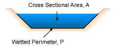
The cross sectional area and wetted perimeter of the channel are given by |
|||||||||||||||||||||||||||||||||||||||||||||||||||||||||||||||||||||||||||||||||||||||||||||||||||||||||||||||||||||||||||||||||||||||||||||||||||||||||||||||||||||||||||||||||||||||||||||||||||||||
 Hydraulic Depth |
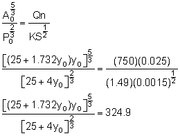
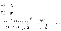
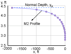
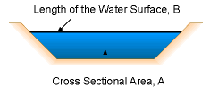
By trial and error, it is found that the normal depth, yo, is 4.42 ft. Fr = 1 = Vc/(gLc)0.5 where the hydraulic depth is given by Lc = Ac/Bc as shown in the figure. Note that the subscript c represents the critical depth condition. Substituting the definition of the hydraulic depth and Vc = Q/Ac into the above equation yields: By trial and error, it is determined that the critical depth yc = 2.83 ft. Since yo > yc, from the water surface profiles table, it can be concluded that the slope is mild, and the water surface has the profile of M2. The direct step method is then used to compute the actual water surface profile. Computations are done through a spreadsheet, as summarized in the following table: |
|||||||||||||||||||||||||||||||||||||||||||||||||||||||||||||||||||||||||||||||||||||||||||||||||||||||||||||||||||||||||||||||||||||||||||||||||||||||||||||||||||||||||||||||||||||||||||||||||||||||
Table: Direct Step Method
Using a Spreadsheet
|
||||||||||||||||||||||||||||||||||||||||||||||||||||||||||||||||||||||||||||||||||||||||||||||||||||||||||||||||||||||||||||||||||||||||||||||||||||||||||||||||||||||||||||||||||||||||||||||||||||||||
|
| The computations start from the critical depth (yc = 2.8 ft), and proceed upstream to the normal depth (yo = 4.4 ft). The velocity and the specific energy are determined from V = Q/A and E = y + V2/2g, respectively. The slope of the energy grade line is given by The distance to the assumed water surface elevation is computed by and the last column (Sum Δx) is simply the cumulative distance along the channel. The water surface profile is shown in the figure. |
|||||||||||||||||||||||||||||||||||||||||||||||||||||||||||||||||||||||||||||||||||||||||||||||||||||||||||||||||||||||||||||||||||||||||||||||||||||||||||||||||||||||||||||||||||||||||||||||||||||||
Practice Homework and Test problems now available in the 'Eng Fluids' mobile app
Includes over 250 free problems with complete detailed solutions.
Available at the Google Play Store and Apple App Store.

