| Ch 4. Fundamental Laws (Integral Anal.) | Multimedia Engineering Fluids | ||||||
|
Conservation Mass |
Linear Momentum |
Moment of Momentum |
Conservation Energy |
||||
| Moment of Momentum Equation | Case Intro | Theory | Case Solution |
| Chapter |
| 1. Basics |
| 2. Fluid Statics |
| 3. Kinematics |
| 4. Laws (Integral) |
| 5. Laws (Diff.) |
| 6. Modeling/Similitude |
| 7. Inviscid |
| 8. Viscous |
| 9. External Flow |
| 10. Open-Channel |
| Appendix |
| Basic Math |
| Units |
| Basic Equations |
| Water/Air Tables |
| Sections |
| Search |
| eBooks |
| Dynamics |
| Fluids |
| Math |
| Mechanics |
| Statics |
| Thermodynamics |
| Author(s): |
| Chean Chin Ngo |
| Kurt Gramoll |
| ©Kurt Gramoll |
|
|
|||||
|
The basic concepts of angular momentum and torque will first be introduced. The moment of momentum equation is then stated for a control volume along with an illustration of its applications. |
|||||
|
Angular Momentum and Torque |
||||
|
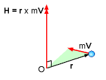
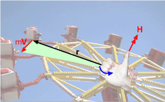
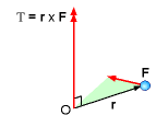
The angular momentum, H, of a particle about a reference point O is the cross product between the position vector, r, and the momentum of the system, mV, or in equation form, H = r × mV where m is the mass of the system, and V is the velocity of the system. The direction of the angular momentum is perpendicular to the plane containing the position vector and velocity vector, and it can be determined by using the right hand rule, as shown in the figure. The angular momentum and torque or moment of a particle are related. Recall, the torque, T, is given by the cross product of the position vector and the force vector: T = r × F The force could also be written as ma and using the chain rule as, T = r × m dv/dt =d(r × mv)/dt Thus, for a particle, the cross product of the position and force vectors is equal to the momentum rate of change, or r × F = dH/dt |
||||
| Moment of Momentum Equation |
|||||
|
|
The moment of momentum equation is also referred to as the angular momentum equation. The moment of momentum equation for a fixed and nondeforming control volume can be derived using by taking a material derivative of the angular momentum of a particle (omitted here), which will give
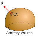
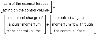
where r is the position vector (about a reference point), V is the absolute velocity of the fluid, and n is the outward unit normal vector. For steady flow, the first term on the right hand side of the moment of momentum equation vanishes. The term V·n will be positive when the flow is out of the control volume while it is negative when the flow is into the control volume (see another section for more discussion). The directions of the quantities r×F and r×V are determined by the right hand rule described previously. The moment of momentum equation can be stated in words as follows: |
||||
|
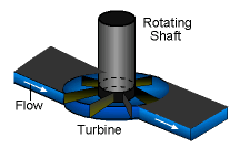
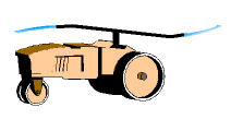
The moment of momentum equation can be applied to analyze rotating systems, such as turbines, sprinklers, and fans. In analyzing such systems, the vector form of the equation is often resolved into scalar form, and only the direction along the axis of rotation is considered. Take the lawn sprinkler as shown in the figure for example. For steady flow, the moment of momentum equation reduces to |
||||
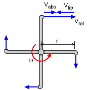 Velocity Relationships: Vtip - Nozzle Tip Velocity ( = ωr) Vrel - Fluid Velocity Relative to Nozzle Vabs - Absolute Velocity from Ground |
But notice, there are two possible velocities with this formulation. Vrel is the velocity relative to the rotating nozzle, as if one is standing on the nozzle head. Next, Vabs is the absolute velocity as viewed from the non-rotating frame of reference (i.e. the ground). So why two velocities? Due to the conservation of mass, the mass flow rate, dm/dt is constant, and thus ρVrel must also be constant. Vrel is constant for a non-accelerating system. The Vabs is the rate the mass is really moving as compared to the ground and this drives the rotating arm. It is critical that the relationship between Vabs and and Vrel is understood and used correctly. They are related as Vabs = Vrel + Vtip where Vtip is usually in the opposite direction, and thus negative. |
||||
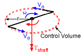 Moment of Momentum Analysis of a Lawn Sprinkler |
Generally, the basic steady state angular moment equation is written with separate terms for fluid coming in and going out (velocity is assumed perpendicular to the inlet or outlet area, and area does not change) giving This form is for fixed, nondeforming control volumes. For rotating system, the absolute velocity must be used. Along the axis of rotation, the above equation can also be written in scalar form for outlet only systems as simply Tshaft = -r Vθ dm/dt where Tshaft is the torque of the shaft, Vθ is the tangential velocity of the fluid, and dm/dt (=ρAVrel) is the total mass flow out of the control volume. Notice, this is a scalar equation, and the minus sign means that the shaft torque opposes the rotating arms. This equation assumes no fluid is coming into the system except at the center of rotation (i.e. a sprinkler type system). |
||||
| Shaft Power |
|||||
In some cases, the shaft power is needed to determine a pump size or turbine output. Power is simply the work per unit time. For rotating systems, this can be expressed as where ω is the angular velocity of the shaft. |
|||||
Practice Homework and Test problems now available in the 'Eng Fluids' mobile app
Includes over 250 free problems with complete detailed solutions.
Available at the Google Play Store and Apple App Store.
