| Ch 5. Beam Deflections | Multimedia Engineering Mechanics | ||||||
|
Integration of Moment |
Integration of Load |
Method of Superposition |
Indeterminate Beams |
||||
| Indeterminate Beam Structures | Case Intro | Theory | Case Solution | Example |
| Chapter |
| 1. Stress/Strain |
| 2. Torsion |
| 3. Beam Shr/Moment |
| 4. Beam Stresses |
| 5. Beam Deflections |
| 6. Beam-Advanced |
| 7. Stress Analysis |
| 8. Strain Analysis |
| 9. Columns |
| Appendix |
| Basic Math |
| Units |
| Basic Equations |
| Sections |
| Material Properties |
| Structural Shapes |
| Beam Equations |
| Search |
| eBooks |
| Dynamics |
| Fluids |
| Math |
| Mechanics |
| Statics |
| Thermodynamics |
| Author(s): |
| Kurt Gramoll |
| ©Kurt Gramoll |
|
|
||
|
The new storage area had three supports, roller shear connection at the left edge, a standard pin connection at the center and a common fixed connection at the right edge. The load is 50 lb/in along the beam length. This structure has two redundant supports so it is indeterminate to second degree. This will require two compatibility equations relating either the deflection or the rotation. A good choice in solving this problem is to use superposition. The beam can be simplified into several common beams that have deflection equations given in the Beam Equations Appendix. |
||
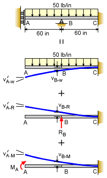 Beam and Loading is Simplified using Superposition |
Simplifying the Beam Problem |
|
|
To solve this problem with superposition, the beam needs to be simplified into basic beams. There are numerous possibilities when splitting the beam, but the new basic beam types need to be listed in the appendix. One possible simplification is to release the left and center supports. This gives a basic cantilever beam with a continuous uniform distributed load. This beam is listed in the appendix. Because the two left supports where released, they need to be added back as unknown forces as their own separate cantilever beams. Again, the beam and loading need to be listed in the appendix. The center support is replaced with an unknown force, RB. This bends the beam upward. Likewise, the released roller shear connection is replaced with an unknown moment load, MA. Recall, the roller shear connection allows the beam to deflect, but there is no rotation. |
||
| Compatibility Equations |
||
|
The original beam is now three simple beams but there are two unknown loads, RB and MA that cannot be found with static equilibrium equations. This means two additional equations are required. They can be developed from compatibility equations at each of the released support. Even though the supports were released and replaced with unknown loads, the connections still have to meet compatilbility requirements. For this problem, point A cannot rotate, i.e. v´A = 0. This requires that the sum of all the simple beam's rotations at A must be equal to 0, or v´A = v´A-w + v´A-R + v´A-M = 0 Likewise, the sum of all the simple beam's deflections at point B must be equal to 0, or vB = vB-w + vB-R + vB-M = 0 The subscript notation is location and load type. Thus vB-R is the deflection at point B. |
||
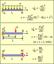 Selected Beam Equations from Appendix (Note, points A and B are not the same as in the problem) |
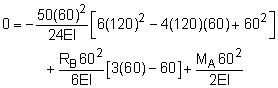
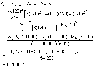
From the Beam Equations Appendix the deflection and slope for any point on the simple beams can be found. They are summarized at the left for convenience. However, for this problem it is actually the reverse as the cantilever beams given in the appendix, and care needs to be taken to to get the correct equation and value. The simple beam deflections and slopes can be used in the previous two compatibility equations. The slope at A is equal to zero, Positive rotation or angle is counter-clockwise. The deflection at B is zero, Positive deflection is assumed to be up. These two equations can be simplified to 120,000 = 15 RB + MA 255,000 = 40 RB + MA The solution to these equations give RB = 5,400 lb MA = 39,000 lb-in |
|
| Point A Deflection |
||
|
|
Notice, the compatibility equations only gave the support reactions, and not the final deflections. However, it is a simple matter of using the reaction values with the simple beam deflection equations to give the final deflection. Once again, the principle of superposition is used to simplify the process. The final deflection is the sum of the three basic equations, or
|
|
| Maximum Bending Stress Check |
||
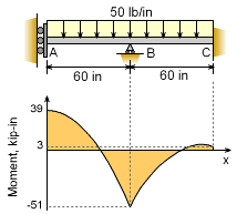 Moment Diagram |
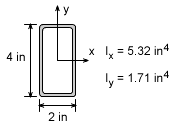
While not required, it is always important to check the maximum bending stress as a safety precaution. Using methods presented in the Shear and Moment Diagrams section, the moment diagram is constructed and shown at the left. The maximum occurs at point B and is -51,000 lb-in. The bending stress is σ = My/I = 51,000 (2) / 5.32 = 19,170 psi This stress level is less than the allowable for structural steel. |
|
Practice Homework and Test problems now available in the 'Eng Mechanics' mobile app
Includes over 500 free problems with complete detailed solutions.
Available at the Google Play Store and Apple App Store.